Control valve of injector

A technology for control valves and injectors, which is applied in the field of control valves and injector control valves. It can solve the problems of limited working pressure of injectors, increased leakage risk of contact surfaces, and high difficulty in manufacturing and processing, so as to reduce opening delay time, The effect of improving the service life and reducing the difficulty of processing

Inactive Publication Date: 2020-07-31
CHANGSHU INSTITUTE OF TECHNOLOGY
View PDF7 Cites 0 Cited by
  • Summary
  • Abstract
  • Description
  • Claims
  • Application Information

AI Technical Summary

Problems solved by technology

[0002] The control valve is an important part of the fuel injector. It can accurately control the opening of the fuel injector and is the key factor affecting the precise control of the fuel injector. Now the injection pressure requirements of the fuel injector are constantly increasing, and the injection pressure is required to be above 200MPa. At the same time, the hydraulic pressure in the cavity of this type of control valve is also continuously increasing. The oil in the control cavity drops from a high pressure (200MPa and above) to 0MPa, which will cause cavitation damage. The higher the oil pressure, the more serious the cavitation damage. The easier the oiler is damaged, the shorter the service life
[0003] In the prior art, for example, the patent structure of the publication number: CN103967666B does not have a structure for controlling the pressure drop of the cavity slowly, and high pressure will cause cavitation damage, thereby limiting the working pressure of this type of injector; publication number: DE10190272B4 patent technical manual attached Image 6 The restrictor (148) and socket valve (302) shown in the figure can reduce cavitation damage, but there are many sealing contact surfaces between parts, which increases a certain risk of leakage; publication number: CN101595297B patent end The ball seat valve (110) also has an inlet (122) with a pre-throttling device (126) and a diffuser (128) arranged between the pre-throttle device (126) and the valve seat (120). ), the diffuser (128) can play a pressure buffer role for high oil pressure, the pressure in the diffuser (128) decreases, and the pressure difference after the outflow in the diffuser (128) decreases, reducing cavitation damage, The one-piece structure in this patent is as attached to its description figure 2 As shown, it is a thin hole at both ends and a thick hole in the middle, so the difficulty of manufacturing and processing is very high, and the diffuser (128) of the split structure in this patent is as attached to its description. image 3 As shown, the difficulty of processing is reduced, but a sealing contact plane is added, which also increases the risk of leakage

Method used


Image

  • Control valve of injector
  • Control valve of injector
  • Control valve of injector

Examples


Embodiment 1

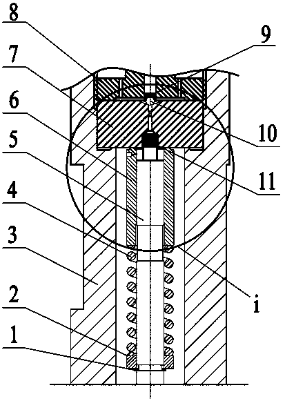
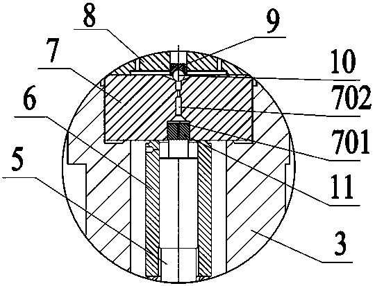
[0037] Example 1, please combine Figure 1 to Figure 3 As shown, the control valve of the injector involved in this embodiment, such as figure 1 As shown, it includes a control plunger 5, a valve sleeve 6, an orifice 7 and a fastening valve seat 8. The fastening valve seat 8 and the injector body 3 are fixed by threaded connection, and the orifice plate 7 is fixed to the injector body 3. Inside, the valve sleeve 6 is sleeved on the outer circumference of the control plunger 5 to cooperate with the control plunger 5 , and the gap between the valve sleeve 6 and the control plunger 5 is between 0.008mm and 0.012mm. The valve sleeve spring 4 acts on the lower end surface of the valve sleeve 6, and the upper end surface of the valve sleeve 6 abuts against the lower end surface of the orifice plate 7. At this time, the control plunger 5, the valve sleeve 6 and the orifice plate 7 form a control cavity. The control valve of the injector also includes a pressure-relief float 11 , wh...

Embodiment 2

[0041] This embodiment 2 is similar to embodiment 1, and the similarities will not be repeated here. The differences of this embodiment are as follows: Figure 10 to Figure 16 As shown, the oil outlet hole 110 of the slow pressure float 11 is a step hole, the near notch end of the oil outlet hole 110 is a large diameter end 112, and the far notch end of the oil outlet hole 110 is a small diameter end 113; 113 aperture ranges from 0.15mm to 0.38mm, preferably ranges from 0.2mm to 0.3mm, and in this embodiment is between 0.2mm to 0.25mm, and the maximum oil outlet aperture range of the slow pressure floating column 11 is from 2mm to 2.5mm; slow pressure The outer peripheral surface of the floating column 11 is provided with a DLC anti-friction coating.

Embodiment 3

[0043] This embodiment 3 is similar to embodiment 1 and embodiment 2, and the similarities will not be repeated here. The differences of this embodiment are as follows: Figure 17 As shown, the diameter of the slow pressure floating column 11 is larger than that in the embodiment 1 and embodiment 2, and the diameter range of the slow pressure floating column 11 is between 3.6mm and 4mm in the present embodiment, and the orifice in the present embodiment is out. The sealing method of the oil hole 701 adopts a planar valve sealing structure in which the sealing column 12 cooperates with the upper end surface of the orifice plate 7 .


PUM


Abstract

The invention discloses a control valve of an injector. The control valve comprises an ejector body, a control plunger, a valve sleeve, an orifice plate and a fastening valve seat. The orifice plate,the valve sleeve and the control plunger form a control cavity. The control valve of the injector also comprises a pressure relief floating column, and the pressure relief floating column is cylindrical and arranged on the upper end face of the control plunger. The end, close to the control plunger, of the pressure relief floating column is provided with a notch part penetrating through the circumferential surface, and an oil outlet hole is formed in the other end of the pressure relief floating column. The oil outlet hole communicates with the notch part to form a connection channel, the orifice plate is provided with a constraint hole matched with the pressure relief floating column, the constraint hole communicates with an orifice plate oil outlet hole of the orifice plate, and the pressure relief floating column can move up and down in the constraint hole. According to the control valve, the problem of cavitation damage of the high-pressure injector can be solved, the service lifeof the injector is prolonged, and the action response is accelerated.

Description

technical field [0001] The invention relates to a control valve, in particular to a control valve of an injector, and belongs to the technical field of high-pressure common rail fuel injection. Background technique [0002] The control valve is an important part of the fuel injector. It can precisely control the opening of the fuel injector and is the key factor affecting the precise control of the fuel injector. Now the injection pressure requirements of the fuel injector are constantly increasing, and the injection pressure is required to be above 200MPa. At the same time, the hydraulic pressure in the cavity of this type of control valve is also continuously increasing. The oil in the control cavity drops from high pressure (200MPa and above) to 0MPa, which will cause cavitation damage. The higher the oil pressure, the more serious the cavitation damage. The easier the oiler is damaged, the shorter the service life. [0003] In the prior art, for example, the patent stru...

Claims


Application Information

Patent Timeline
Patent Type & Authority Applications(China)
IPC IPC(8): F02M51/06F02M61/06F02M61/16F02M61/18
CPCF02M51/061F02M61/06F02M61/161F02M61/18
Inventor 许广举李铭迪赵洋胡焰彬林玲刘帅
Owner CHANGSHU INSTITUTE OF TECHNOLOGY
Why Eureka
Try Eureka