
Multifunctional glass cup making machine

A glass, multi-functional technology, applied in the field of mechanical equipment, to achieve the effect of fast speed, cost reduction and stable quality

Inactive Publication Date: 2015-03-25
施鹏宇
View PDF5 Cites 5 Cited by
  • Summary
  • Abstract
  • Description
  • Claims
  • Application Information

AI Technical Summary

Problems solved by technology

[0003] In order to overcome the disadvantages of the above problems, the present invention provides a multifunctional glass machine. The multifunctional glass machine is equipped with a pressure reducing plate at the rear of the automatic chuck, and the pressure reducing plate can ensure that the clamping block will not pinch the glass There is a steering wheel in the middle of the rocker arm, and there are long slots on the head of the rocker arm that can replace various glass shapes. In order to reduce noise and vibration and ensure the quality of the glass, a small Cylinder, the small cylinder can act as a buffer for the skateboard. There is a chain sprocket at the rear of the machine head to make the embossing die rotate continuously, which solves the phenomenon of frequent collision of teeth. The embossing on the rocker arm and the machine head The combination of molds can deform and seal the glass, and the combination of the rocker arm and the cup mold of the glass can deform the thick bottom of the glass to achieve the purpose of one machine with multiple functions. cost, improve production efficiency

Method used


Image

  • Multifunctional glass cup making machine
  • Multifunctional glass cup making machine
  • Multifunctional glass cup making machine

Examples


Embodiment Construction

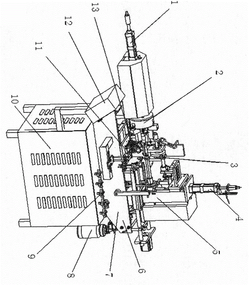
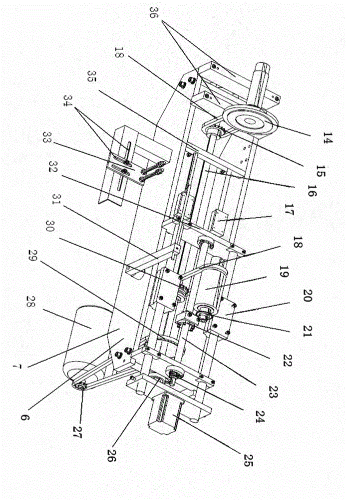
[0014] exist figure 1Among them, the power box 10 is made of angle iron and iron sheet, and heat dissipation holes are arranged on the iron sheet, and the frame 7 is made of iron plate and square iron, and the right side of the frame 7 is provided with a machine head 5, which is pressed with a Front vertical cylinder 4 and embossing die 3, in the middle part of frame 7, there are iron plate 6, fuel injection frame, burner 13 and horizontal dragging device 11, and there are automatic chuck 2 and horizontal adjustable on the left side of frame. Cylinder 1, presses the switch 9 that has liquefied petroleum gas in the upper middle part of power box 10, is placed with oil storage tank 8 on the right side, is pressed with microcomputer 12 on the left side. The top of frame 7 is welded with square iron, long fixed plate and support plate, is welded with two small guide rods between square iron and support plate, is pressed with small linear slider on the small guide rod, between two ...


PUM


Abstract

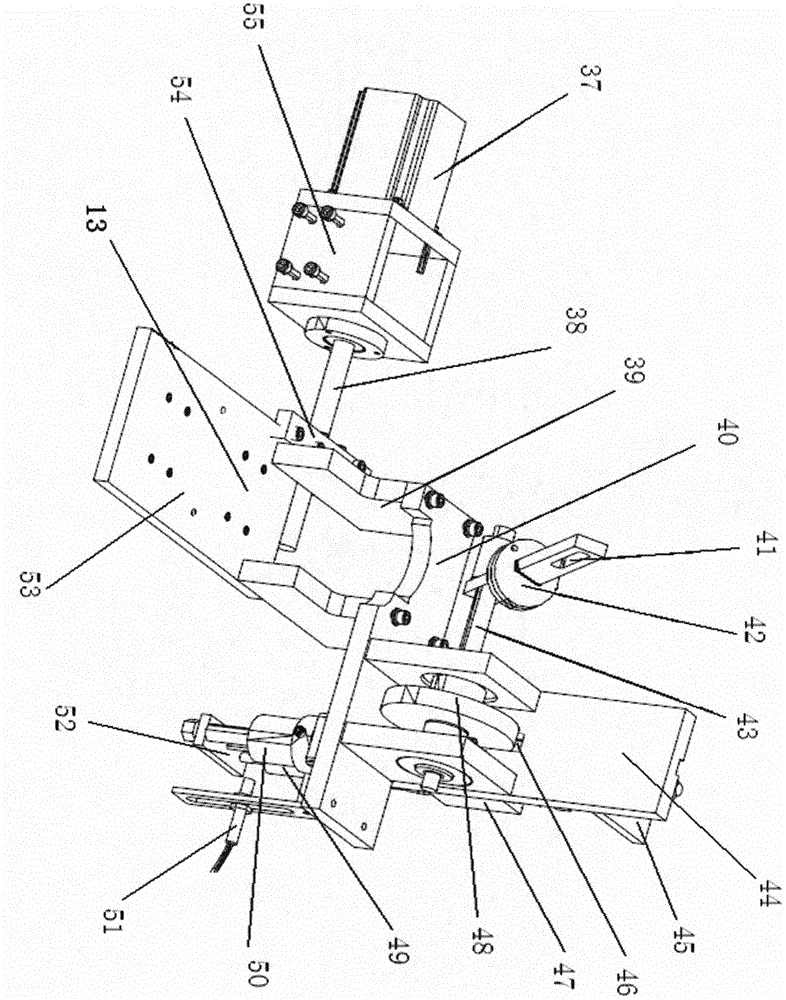
The invention discloses a multifunctional glass cup making machine. A power box is made of angle iron and sheet iron, a frame is made of sheet iron and square iron, a nose is arranged on the right side of the frame, and a front vertical cylinder and an embossing mold are arranged on the nose; an iron plate, an oil spray rack, a fire head and a transverse dragging device are arranged at the middle of the frame; an automatic chuck and a transverse adjustable cylinder are arranged on the left side of the frame; a liquefied gas switch is arranged at the middle upper part of the power box, an oil storage tank is arranged on the right side of the power box, and a microcomputer is arranged on the left side of the power box; a main shaft is arranged at the lower part of the frame, an upper chuck sprocket and a lower chuck sprocket are arranged at two ends of the main shaft, and a transmission sprocket is arranged at the middle part of the main shaft; a transverse carriage is arranged on two small linear slide blocks, a steering wheel and an elongated slot are arranged on a rocker arm, a pull rod is arranged in the center of the automatic chuck, a spring is arranged on the pull rod, a pressure-relief panel is provided with three circular holes, a thrust bearing is arranged on the pressure-relief panel, a connecting column is arranged on the pull rod of the transverse adjustable cylinder, two small cylinders are arranged on a middle fixed plate, an upper fixed plate is provided with three slot holes, an upper shaft and a middle shaft are arranged on a shaft fixing plate, and a tensioning sprocket is arranged on a long plate.

Description

technical field [0001] The invention relates to a mechanical device, especially a multifunctional glass machine suitable for people to make glasses. Background technique [0002] At present, known glass cup machine is made up of motor, air pump, cylinder, sprocket wheel, chain, axle, carriage, three-jaw chuck, gear. When pressing the glass mouth and screw thread, due to the cooperation between the threaded mold and the inner mold in the rotating state, tooth collisions often occur, causing the glass to be damaged and scrapped. The two most important steps are to seal the bottom of the glass or burn the bottom. In the process steps, the ordinary three-jaw chuck is used to clamp the glass at present. Because it is manual operation, the processing speed is affected. In addition, the manual operation is not easy to control the clamping force, and it is easy to be broken or not clamped tightly, which increases the cost of the product. Glass deformation and sealing are processed ...

Claims


Application Information

Patent Timeline
Patent Type & Authority Applications(China)
IPC IPC(8): C03B23/045
CPCY02P40/57
Inventor 施鹏宇
Owner 施鹏宇
Learn More