Vacuum quenching furnace

A vacuum quenching furnace and vacuum technology, used in quenching devices, heat treatment equipment, manufacturing tools, etc., can solve the problems of inability to meet the quenching requirements of large quantities of materials, low production efficiency, limited furnace capacity, etc., to achieve streamlined operations, Improve production efficiency and meet the effect of mass quenching

Active Publication Date: 2015-03-25
ADVANCED FOR MATERIALS & EQUIP
View PDF5 Cites 7 Cited by
  • Summary
  • Abstract
  • Description
  • Claims
  • Application Information

AI Technical Summary

Problems solved by technology

However, due to the small size of the heating zone of the device, the furnace loading capacity is limited, which cannot meet the quenching requirements of large quantities of materials; in addition, because the device has to wait for the furnace tank to cool down before continuing to charge the furnace after quenching, the production efficiency is relatively low

Method used


Image

  • Vacuum quenching furnace
  • Vacuum quenching furnace
  • Vacuum quenching furnace

Examples


Embodiment Construction

[0021] In order to enable those skilled in the art to better understand the technical solutions in the present application, the technical solutions in the embodiments of the present application will be clearly and completely described below in conjunction with the drawings in the embodiments of the present application. Obviously, the described The embodiments are only some of the embodiments of the present application, but not all of them.

[0022] Based on the embodiments in this application, all other embodiments obtained by persons of ordinary skill in the art without creative efforts shall fall within the scope of protection of this application.

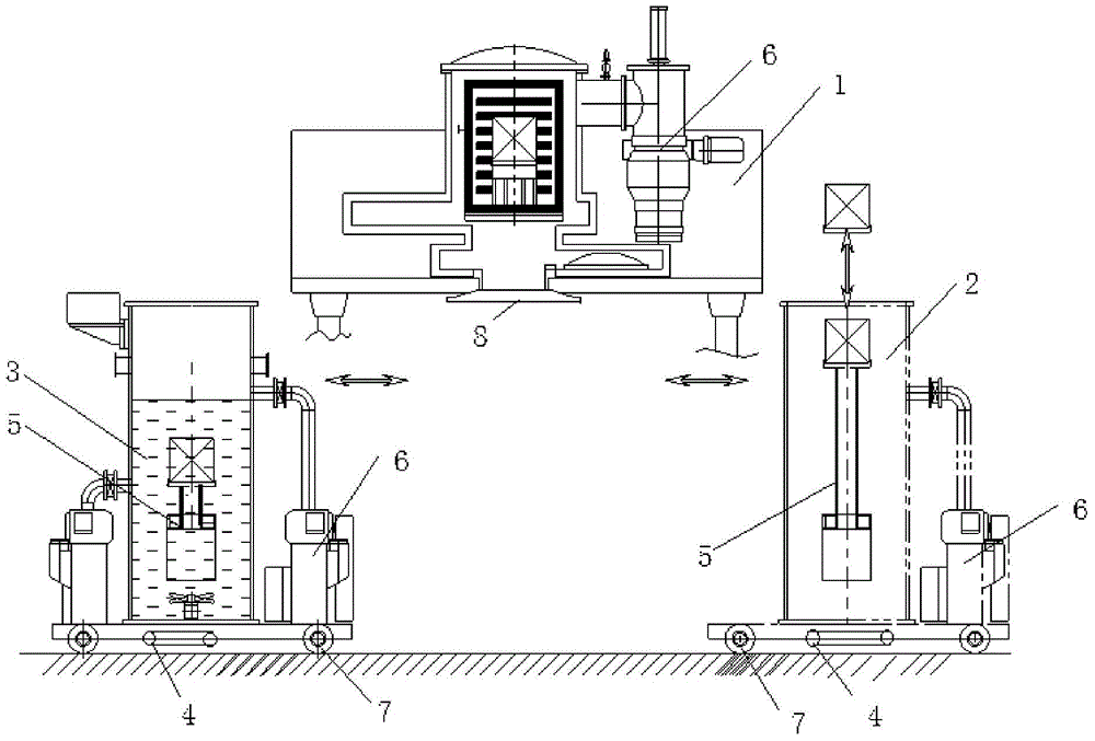
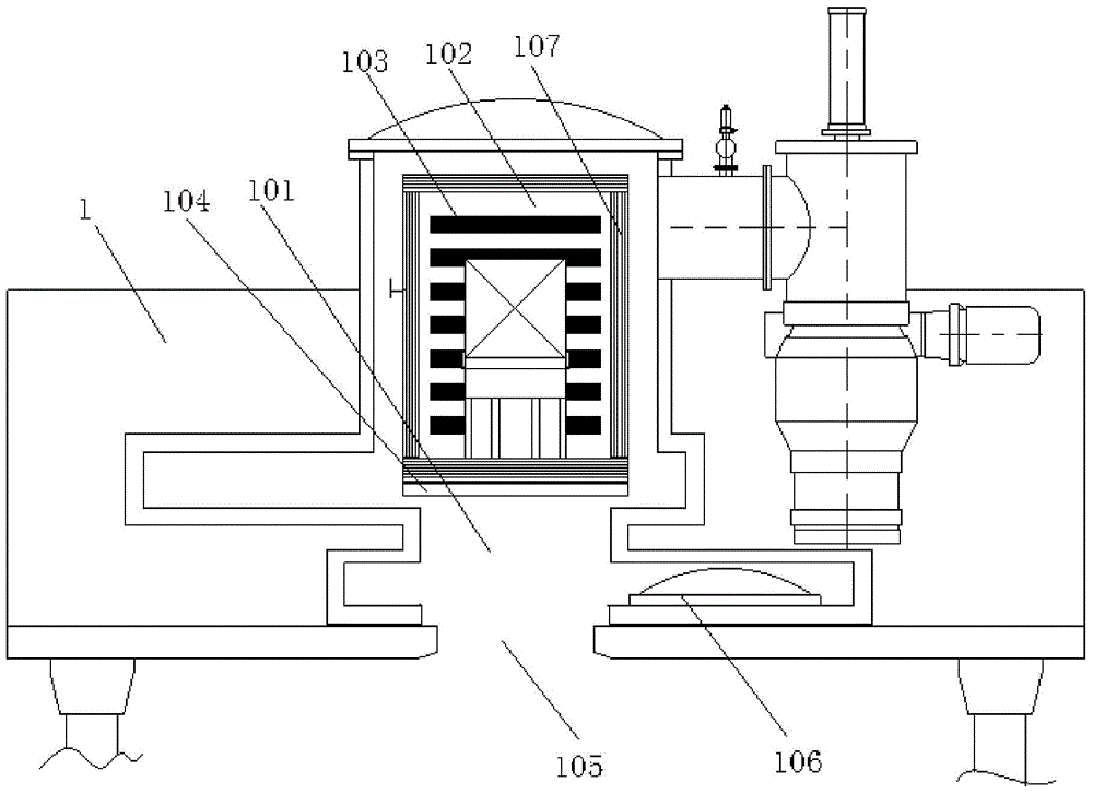
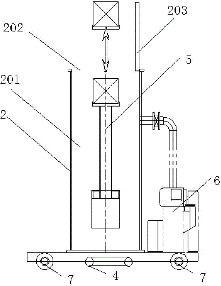
[0023] Referring to the accompanying drawings, the accompanying drawings provide a specific embodiment of a vacuum quenching furnace. As shown in the accompanying drawings, the vacuum quenching furnace includes a heating chamber 1, a charging chamber 2 and a quenching chamber 3, wherein the heating chamber 1 is mainly used for Pr...


PUM


Abstract

The invention discloses a vacuum quenching furnace. The vacuum quenching furnace comprises a heating chamber, a charging chamber and a quenching chamber, wherein a heating cavity is formed in the heating chamber, a heating box is fixed in the heating cavity, a heating plate is arranged in the heating box, a thermal insulation load bearing door is arranged at the bottom of the heating box, the bottom of the heating cavity is provided with a first material inlet and outlet provided with a first seal door, and the first seal door is arranged under the thermal insulation load bearing door; a charging cavity for containing materials is formed in the charging chamber, and the top of the charging cavity is provided with a second material inlet and outlet provided with a second seal door; a quenching cavity is formed in the quenching chamber, the quenching cavity is connected with a water tank and a water ring pump, the top of the quenching cavity is provided with a third material inlet and outlet provided with a third seal door, material lifting devices are arranged in the charging cavity and the quenching cavity respectively, and the heating chamber, the charging chamber and the quenching chamber are each connected with a vacuumization device. The vacuum quenching furnace can effectively shorten time delay and meet the requirement for quenching of a large batch of materials.

Description

technical field [0001] The present invention relates to the technical field of heat treatment equipment, more specifically, to a vacuum quenching furnace. Background technique [0002] Quenching is a heat treatment process, which refers to a metal heat treatment process in which the metal workpiece is first heated to a certain temperature, then kept for a period of time, and then immediately immersed in the quenching medium for rapid cooling. The purpose of quenching is to transform the austenite in the metal into martensite or bainite, and then cooperate with tempering at different temperatures to greatly improve the rigidity, hardness, wear resistance, fatigue strength and toughness of the metal, so as to meet the Different use requirements for various mechanical parts and tools. The quenching process usually needs to be carried out in a specific device. Among them, the vacuum quenching furnace is a common quenching device. Due to the good heat insulation and sealing effe...

Claims


Application Information

Patent Timeline
Patent Type & Authority Applications(China)
IPC IPC(8): C21D1/62C21D1/773
CPCC21D1/62C21D1/773
Inventor 马卫东戴煜彭泽云刘红军
Owner ADVANCED FOR MATERIALS & EQUIP
Why Eureka
Try Eureka