Large-diameter SMW (soil mixing wall) pile machine

A technology of construction method pile and large diameter, which is applied in sheet pile wall, foundation structure engineering, construction, etc., can solve the problems of inability to manufacture SMW piles and the length of stirring wings cannot be large.

Inactive Publication Date: 2015-03-25
孔月洽
View PDF5 Cites 44 Cited by
  • Summary
  • Abstract
  • Description
  • Claims
  • Application Information

AI Technical Summary

Problems solved by technology

[0002] At present, the SMW construction method pile driver for building the underground diaphragm wall, since the three drill rods of the pile driver are driven by a gearbox, the distance between every two drill rods is fixed, which determines that the length of the stirring wing cannot be greater than The distance between two adjacent drill rods, the radius of each single pile pile body that makes with such pile machine is all less than the distance between two adjacent drill rods, the radius that cannot manufacture each single pile pile body Large diameter SMW piles greater than the distance between two adjacent drill pipes

Method used


Image

  • Large-diameter SMW (soil mixing wall) pile machine
  • Large-diameter SMW (soil mixing wall) pile machine

Examples


specific Embodiment

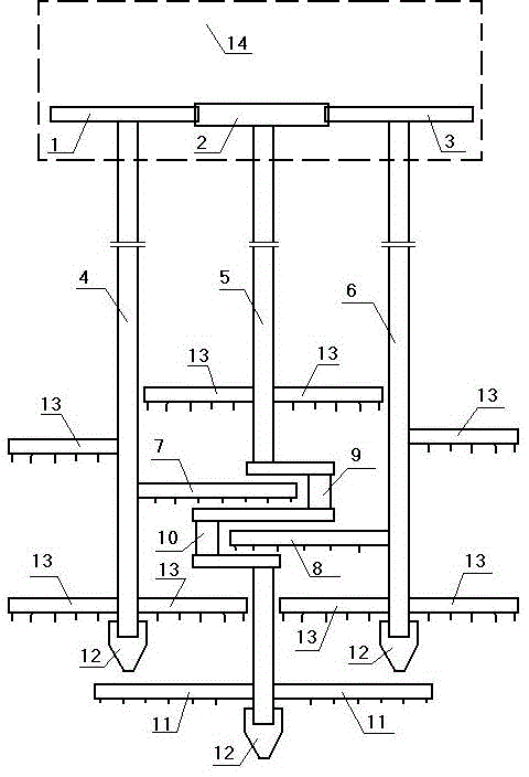
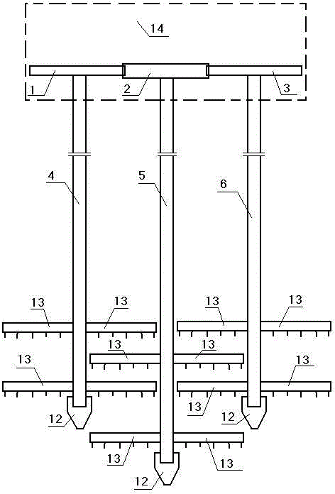
[0012] Accompanying drawing is a kind of specific embodiment of the present invention, and this embodiment gear A1, gear B2, gear C3 are arranged in the gearbox 14, and the lower end of gear A is fixed with drilling rod A4, and the left side of the lower part of drilling rod A is fixed with two short stirring wings 13. A long stirring wing A7 and a short stirring wing are fixed on the right side of the lower part of the drill pipe A; a drill pipe C6 is fixed on the lower end of the gear C, two short stirring wings are fixed on the right side of the lower part of the drill pipe C, and a long stirring wing is fixed on the left side of the lower part of the drill pipe C B8 and a short stirring wing; the lower end of the gear B is fixed to the drill pipe B5, and the left and right sides of the lower part of the drill pipe B are respectively fixed with a short stirring wing. A long stirring wing C11 is respectively fixed on the left and right sides of the lower drill rod.

[0013] ...


PUM


Abstract

Disclosed is a large-diameter SMW (soil mixing wall) pile machine. A gear A, a gear B and a gear C are arranged in a transmission, a drill rod A is fixed to the lower end of the gear A, two short stirring blades are fixed to the left of the lower portion of the drill rod A, a long stirring blade A and a short stirring blade are fixed to the right of the lower portion of the drill rod A; a drill rod C is fixed to the lower end of the gear C, two short stirring blades are fixed to the right of the lower portion of the drill rod C, and a long stirring blade B and a short stirring blade are fixed to the left of the lower portion of the drill rod C; a drilling rod B is fixed to the lower end of the gear B, a short stirring blade is fixed to each of the left and right sides of the lower portion of the drill rod B, a crankshaft with a crank pin A and a crank pin B are fixed on the drill rod on the lower portions of the short stirring blades, and a long stirring blade C is fixed to each of the left and right of the drill rod of the lower portion of the crankshaft.

Description

technical field [0001] The invention relates to a pile driver, in particular to a large-diameter SMW method pile driver for building an underground continuous wall. Background technique [0002] At present, for the SMW construction method pile driver for building the underground diaphragm wall, since the three drill rods of the pile driver are driven by a gearbox, the distance between every two drill rods is fixed, which determines that the length of the stirring wing cannot be greater than The distance between two adjacent drill rods, the radius of each single pile pile body that makes with such pile machine all is less than the distance between two adjacent drill rods, the radius of every single pile pile body that cannot be manufactured Large diameter SMW piles greater than the distance between two adjacent drill pipes. Contents of the invention [0003] The present invention makes up for the above shortcomings of the SMW construction method pile driver, and provides a...

Claims


Application Information

Patent Timeline
Patent Type & Authority Applications(China)
IPC IPC(8): E02D5/46
CPCE02D5/46E02D2250/0038
Inventor 张璐
Owner 孔月洽
Why Eureka
Try Eureka