
Hydraulic energy saving device of oil pumping unit

An energy-saving device and pumping unit technology, applied in fluid pressure actuation devices, mechanical equipment, actuator accumulators, etc., can solve the problems of high peak power of motors and reverse power generation, and can not achieve energy-saving effects, etc., to ensure The effect of long-term normal operation, lower purchase cost, and reduced torque fluctuation

Inactive Publication Date: 2015-03-25
SHAANXI YUHANG ELECTRONICS
View PDF0 Cites 0 Cited by
  • Summary
  • Abstract
  • Description
  • Claims
  • Application Information

AI Technical Summary

Problems solved by technology

However, no matter what kind of balance modification method is adopted, the load torque curve of the pumping unit is always an irregular curve, resulting in a large peak power and reverse power generation phenomenon of the motor, which cannot achieve the best energy-saving effect

Method used


Image

  • Hydraulic energy saving device of oil pumping unit

Examples


Embodiment Construction

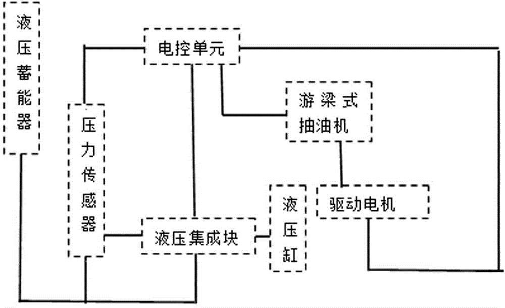
[0015] A hydraulic energy-saving device for a pumping unit is composed of two parts: a mechanical hydraulic assembly and an electric control unit. Wherein, the mechanical hydraulic assembly is composed of a hydraulic cylinder, a hydraulic accumulator, a pressure sensor and a hydraulic integrated block, and the hydraulic accumulator is connected to the pressure sensor and the hydraulic integrated block respectively; the pressure sensor and the hydraulic integrated block are connected to the electronic control unit . The electric control unit is composed of a DSP micro-processing chip, a data acquisition circuit and a control circuit, and the electric control unit is also connected to a hydraulic cylinder. The upper hinge seat of the piston rod of the hydraulic cylinder can be connected with the beam of the external equipment pumping unit and installed at the front end of the pumping unit.

[0016] The hydraulic energy-saving device is connected with the pumping unit beam throu...


PUM


Abstract

The invention aims to provide a hydraulic energy saving device of an oil pumping unit. By the adoption of the hydraulic energy saving device, negative work energy can be recycled. The hydraulic energy saving device of the oil pumping unit is composed of a mechanical-hydraulic assembly and an electronic control unit. The hydraulic energy saving device prolongs the service life of the oil pumping unit and reduces the acquisition cost of the oil pumping unit. When the hydraulic energy saving device breaks down and needs to be maintained, the normal use of the original oil pumping unit is not influenced, so that the long-term normal operation of the oil pumping unit is guaranteed, maintenance of the hydraulic energy saving device cannot influence the yield of an oil well, and the hydraulic energy saving device is suitable for energy-saving transformation of a conventional beam-pumping unit.

Description

technical field [0001] The invention relates to the field of petrochemical technology, in particular to a hydraulic energy-saving device for a pumping unit. Background technique [0002] Conventional beam pumping units have the problems of "big horse-drawn carts" and high energy consumption. In order to overcome this problem, Xinjiang Oilfield carried out a balance transformation on the beam pumping unit. One is to add a balance block to the crank Crank balance, the second is to add a balance block at the end of the beam, that is, the balance of the beam, and the third is to add a balance block at the end of the crank and the end of the beam, that is, composite balance. Through these three methods of balance transformation, the balance degree of the pumping unit has been effectively improved, from the initial balance degree pass rate of less than 30% to more than 70% now, and the average active power of the motor has been significantly reduced. However, no matter what kind ...

Claims


Application Information

Patent Timeline
IPC IPC(8): E21B43/00F15B1/02
CPCE21B43/00F15B1/02F15B2201/00
Inventor 郝青
Owner SHAANXI YUHANG ELECTRONICS
Learn More