
Power supply circuit and power supply mode of leakage protector with power factor less than 0.1 PF

A leakage protector and power factor technology, applied in emergency protection circuit devices, circuit devices, emergency protection devices with automatic disconnection, etc., to achieve the effect of reducing active power consumption

Pending Publication Date: 2022-06-17
浙江诚富电器科技有限公司
View PDF0 Cites 0 Cited by
  • Summary
  • Abstract
  • Description
  • Claims
  • Application Information

AI Technical Summary

Problems solved by technology

[0003] The active power consumption of existing leakage protectors is above 0.2W. Due to different market demands, especially export products limit the power consumption of the whole machine, the active power consumption of leakage protectors needs to be less than 0.1W gradually.

Method used


Image

  • Power supply circuit and power supply mode of leakage protector with power factor less than 0.1 PF

Examples

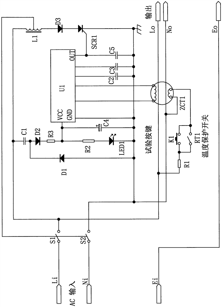

Embodiment 2

[0023] Based on the first embodiment, the difference from the first embodiment is that the loop diode D1 can be replaced by a voltage regulator tube, and the voltage regulator tube can be used instead of the loop diode D1 and has the same effect, which improves the leakage current of the power factor less than 0.1PF The adaptability of the protector power supply circuit and power supply mode.

[0024] To sum up, the power supply circuit and power supply method of the leakage protector whose power factor is less than 0.1PF, when using, connect one or more capacitors in series or in parallel to form a step-down capacitor C1, and then connect the step-down capacitor C1 in series with the load. On the power supply loop, use the rectifier diode D2 to extract the AC cycle corresponding to the diode connection polarity, and use the loop diode D1 to supply the AC power to the step-down capacitor C1 discharge circuit during the non-working cycle time of the rectifier diode D2, and then ...


PUM

PropertyMeasurementUnit
power factoraaaaaaaaaa

Abstract

The invention relates to a leakage protector power supply circuit with a power factor less than 0.1 PF and a power supply mode, the leakage protector power supply circuit comprises a step-down capacitor C1, a rectifier diode D2, a loop diode D1, a filter capacitor C4 and a leakage protection chip U1, the step-down capacitor C1 is connected in series to a load power supply loop, the step-down capacitor C1 is connected in series to a positive electrode of the rectifier diode D2, and the filter capacitor C4 is connected in series to a negative electrode of the loop diode D1. And the loop diode D1 is electrically connected with the step-down capacitor C1. According to the leakage protector power supply circuit with the power factor smaller than 0.1 PF and the power supply mode, a step-down capacitor C1, a rectifier diode D2, a loop diode D1 and a filter capacitor C4 are used in cooperation, one or more capacitors are connected in series or in parallel to form the step-down capacitor C1, meanwhile, the step-down capacitor C1 is connected to a load power supply loop in series, and meanwhile, the step-down capacitor C1 is matched with the rectifier diode D2, so that the power factor smaller than 0.1 PF is obtained. And a loop diode D1 and a filter capacitor C4 play a role in voltage reduction, so that the active power consumption of the leakage protector is reduced and reaches 0.1 W or below, and the leakage protector is more suitable for market requirements.

Description

technical field [0001] The invention relates to the technical field of leakage protectors, in particular to a power supply circuit and a power supply mode for a leakage protector whose power factor is less than 0.1PF. Background technique [0002] The leakage protector, referred to as the leakage switch, is mainly used to protect people from electric shock when the equipment has a leakage fault. It has overload and short-circuit protection functions. It is used to start the infrequent conversion of the line. [0003] The active power consumption of the existing leakage protectors is more than 0.2W. Due to different market demands, especially the export products limit the power consumption of the whole machine, the active power consumption of the leakage protectors gradually needs to reach below 0.1W. Therefore, we propose a power supply circuit and power supply method for the leakage protector whose power factor is less than 0.1PF. SUMMARY OF THE INVENTION [0004] Aimin...

Claims


Application Information

Patent Timeline
Patent Type & Authority Applications(China)
IPC IPC(8): H02M7/06H02H3/32
CPCH02M7/06H02H3/32
Inventor 倪圣富
Owner 浙江诚富电器科技有限公司
Learn More