Cooling structure for high-temperature rotating wheel disc

A technology of cooling structure and rotating wheel, which is applied in the direction of supporting elements of blades, engine elements, machines/engines, etc., can solve problems such as not being able to meet the high-efficiency cooling of the wheel disk, lowering the temperature of the mainstream gas, and reducing the working ability of the turbine, etc., to achieve extended Thermal fatigue service life, reduce the temperature of the plate body, and optimize the effect of temperature distribution

Active Publication Date: 2015-03-25
中科航空动力(株洲)装备制造研究院有限公司
View PDF8 Cites 5 Cited by
  • Summary
  • Abstract
  • Description
  • Claims
  • Application Information

AI Technical Summary

Problems solved by technology

The cooled gas enters the main flow through the axial gap before and after the wheel disc, and is mixed with the main flow. However, the mixing of the cooling air flow and the main flow will cause mixing loss and lower the temperature of the main flow gas, which will reduce the working ability of the turbine. , affecting the performance of the turbine
Although this method can cool the disk, in order to ensure the overall efficiency of the turbine, the amount of cooling air is strictly controlled and cannot be increased arbitrarily. Usually, the amount of cooling air only meets the requirements of the sealing flow of the disk edge.
The reduction of the amount of cold air limits the cooling efficiency of the surface of the plate through the ordinary forced convection cooling method to enhance heat transfer, and in the case of a small amount of cold air, when the cooling flow is not uniform, the cooling effect is even worse
In addition, when the turbine is working in a non-design state, the cooling air flow may be more insufficient due to the pressure effect, and the simple forced convection cooling method may not meet the high-efficiency cooling requirements of the wheel disc

Method used


Image

  • Cooling structure for high-temperature rotating wheel disc
  • Cooling structure for high-temperature rotating wheel disc
  • Cooling structure for high-temperature rotating wheel disc

Examples


Embodiment Construction

[0027] The present invention will be further described in detail below in conjunction with the examples, the following examples are explanations of the present invention and the present invention is not limited to the following examples.

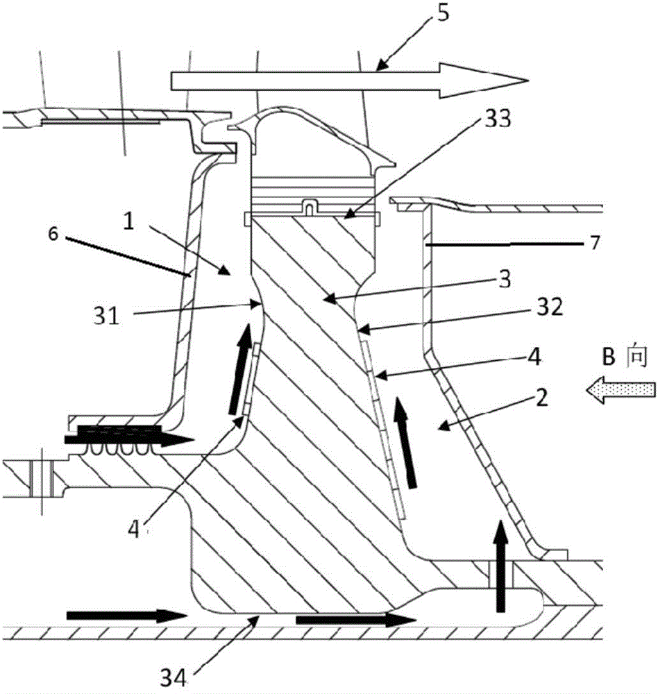
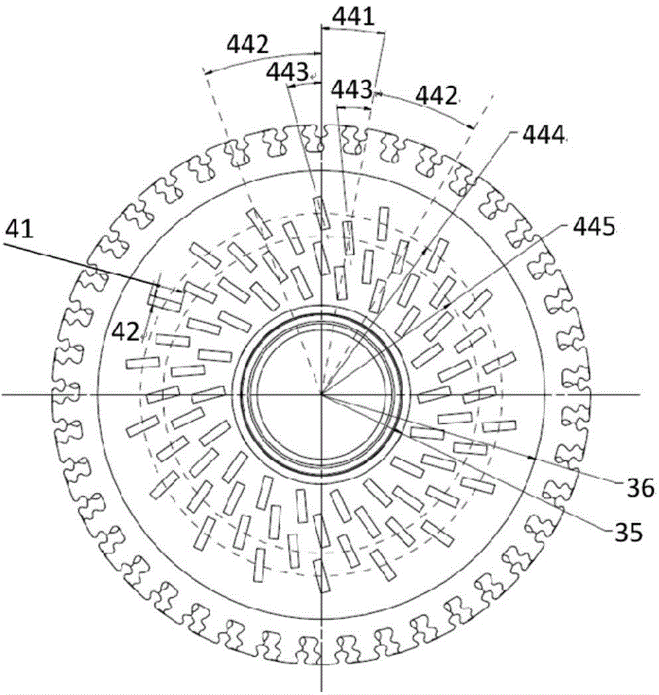
[0028] Such as figure 1 and figure 2 As shown, the cooling structure for the high-temperature rotating wheel of the present invention includes a high-temperature rotating wheel 3, a front baffle 6 and a rear baffle 7, and the front end face 31 of the front baffle 6 and the high-temperature rotating wheel forms a rotating wheel The front cooling chamber 1, the rear baffle plate 7 and the rear end surface 32 of the high-temperature rotating wheel form the rear cooling chamber 2 of the rotating wheel, and the first cooling airflow is formed between the lower end of the front baffle plate 6 and the grate tooth sealing ring of the high-temperature rotating wheel Channel, a second cooling airflow channel is opened between the high-temperature ro...


PUM


Abstract

The invention relates to a cooling structure for a high-temperature rotating wheel disc. The cooling structure can be used for the rotating wheel disc of a ground fuel gas turbine, an aircraft engine and other turbine motors in the high-temperature working environment. Both the front end face and/or the rear end face of the rotating wheel disc are/is provided with a plurality of rows of heat exchanging elements distributed in the radial direction. Each row comprises a plurality of the heat exchanging elements evenly distributed along the axis of the wheel disc in the peripheral direction. The heat exchanging elements in every adjacent rows of the heat exchanging elements are distributed in a staggered mode or in an aligned mode in columns in the radial direction. By means of the heat exchanging elements, the turbulence intensity of an end face flow field of the high-temperature rotating wheel disc can be improved, and the temperature of the surface of the disc body can be further lowered through the reattachment feature that the cooling air flow bypasses the tails of the heat exchanging elements. Compared with a traditional wheel disc structure, the wheel disc cooling mode is simple in structure and easy to implement, the cooling effect of the surface of the wheel disc can be greatly improved by just additionally arranging a heat exchanging rib plate on the surface of the disc body, the wheel disc surface temperature is lowered, and the heat exchanging elements can also be used as dynamic balancing bosses of the rotating wheel disc.

Description

technical field [0001] The invention relates to a cooling structure for gas turbines, turbine engines, etc. using high-temperature rotating discs, which can improve the heat exchange effect on the surface of the discs and reduce the temperature of the disc body without changing the design idea of ​​the original rotating discs. Background technique [0002] The overall weight of the wheel disc increases, which is unfavorable to the overall performance of the engine. Therefore, it is an urgent problem to be solved in the design of advanced turbine disks by adopting an effective cooling structure to increase the heat transfer efficiency, reduce the temperature of the disk body, and then reduce the concentration of thermal stress. [0003] In the past turbines, the cooling of the disk body is generally through the cooling airflow in the front and rear chambers of the disk to flow over the surface of the disk body, and the heat of the disk is taken away by convective heat exchang...

Claims


Application Information

Patent Timeline
Patent Type & Authority Applications(China)
IPC IPC(8): F01D5/08
Inventor 刘军杜强柳光王沛朱俊强
Owner 中科航空动力(株洲)装备制造研究院有限公司
Why Eureka
Try Eureka