
Nozzle of bladeless fan

A bladeless fan and nozzle technology, applied in jet pumps, machines/engines, non-displacement pumps, etc., can solve the problems of large use area, difficult mixing, and affecting air volume, so as to increase the air supply distance, double the airflow velocity, The effect of reducing the number of motor revolutions

Active Publication Date: 2015-03-25
应辉
View PDF4 Cites 11 Cited by
  • Summary
  • Abstract
  • Description
  • Claims
  • Application Information

AI Technical Summary

Problems solved by technology

[0003] 1. The basic airflow injected from the annular exhaust port is relatively scattered and not concentrated, so that when used at a relatively long distance (for example, 3 meters), the flow rate of the airflow generated from the nozzle is low, the air supply effect is not ideal, and it cannot be used quickly and coolly. the purpose of
[0004] 2. The size of the front and rear openings of the annular opening is basically the same size, so that the airflow velocity of the external air when passing through the annular opening depends entirely on the suction force of the basic airflow jetted from the annular exhaust port, so it is difficult to generate high-speed airflow and the basis of jetting The airflow is mixed, which affects the air volume
[0005] 3. The design of the annular channel makes the direction of the basic airflow inside the nozzle circular, which easily causes uneven distribution of the airflow in the channel, which in turn affects the uniformity of the airflow injection
[0006] 4. Existing bladeless fans generally have the problem of high noise when used, especially when the fan is required to provide high-speed airflow, the noise generated by the high-speed rotation of the impeller of the fan assembly cutting air is particularly prominent, which greatly affects the use environment
[0007] 5. The occupied area is large, which is not conducive to placement and storage, etc.

Method used


Image

  • Nozzle of bladeless fan
  • Nozzle of bladeless fan
  • Nozzle of bladeless fan

Examples


Embodiment Construction

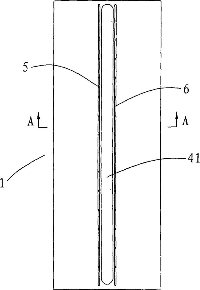
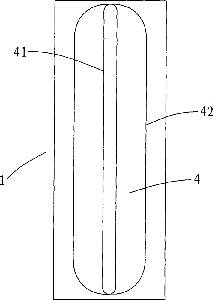
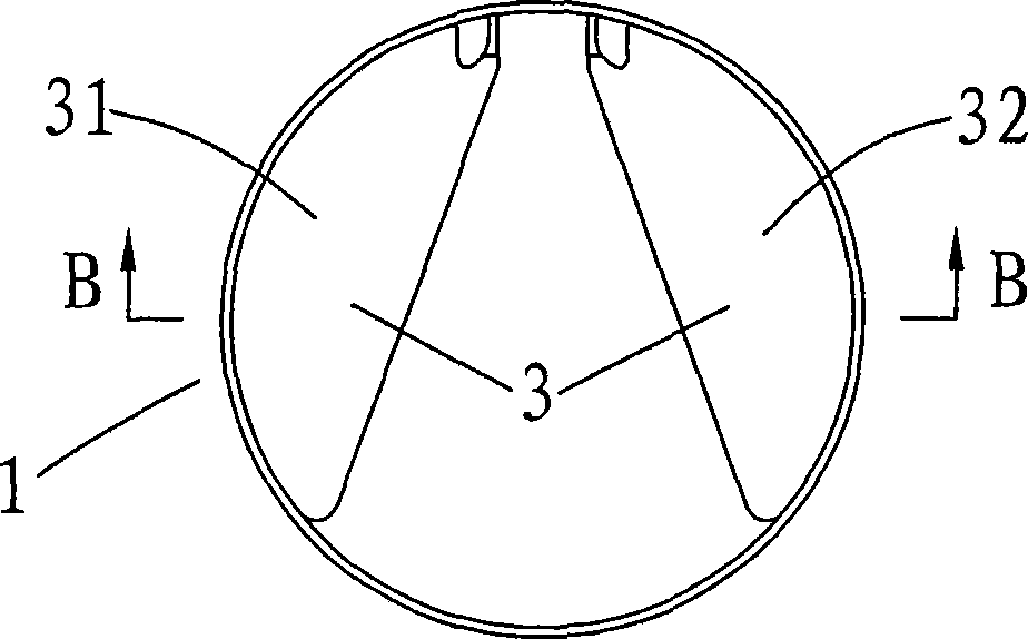
[0031] like Figure 1 to Figure 7 As shown, as a preferred embodiment of the present invention, the bladeless fan nozzle is used in conjunction with the fan assembly that generates the basic airflow, which includes a nozzle body 1, and the nozzle body 1 is provided with a receiving port 2 and an internal passage for receiving the basic airflow 3. The nozzle body 1 is also provided with an air guide port 4 for guiding external air to pass through. The front end of the air guide port 4 is provided with a strip-shaped narrow opening 41, and the rear end of the air guide port 4 is provided with a wide opening 42 whose width is greater than the strip-shaped narrow opening 41. The wide opening 42 can be a waist-shaped opening or a rectangular opening. The definition of the strip-shaped narrow opening 41 means: the opening is made up of two opposite long sides and two opposite short sides, the length of the two long sides is far greater than the width of the two short sides, and the ...


PUM


Abstract

The invention relates to a nozzle of a bladeless fan. The nozzle comprises a nozzle body, a receiving opening used for receiving basic airflow and an inner channel are formed in the nozzle body, the nozzle body is further provided with an air guide opening used for guiding outer air to pass, a strip-shaped narrow opening is formed in the front end of the air guide opening, a wide opening is formed in the rear end of the air guide opening, exhaust openings are formed in the surface of the nozzle body along the periphery of the strip-shaped narrow opening, and the basic airflow received by the inner channel is jet outwards out of the exhaust openings. The nozzle of the bladeless fan is approximately designed in a cylinder shape, the occupied use area is small in the use process, two paths of airflow are jet out of the exhaust openings and are joined to form one path of airflow in front of the nozzle, the jetting speed of the airflow is improved, the air supply distance is increased, and the aim of fast cooling a user can be achieved. Meanwhile, the air guide opening is of a horn structure with the narrow front end and the wide rear end, the airflow flowing speed can be multiplied when the outer air is guided to pass, and therefore the air amount is improved.

Description

Technical field: [0001] The invention relates to the field of fans, in particular to a nozzle of a bladeless fan. Background technique: [0002] At present, most bladeless fan nozzles are designed as annular nozzles, which are provided with an annular channel for receiving the basic airflow and an annular exhaust port for jetting the basic airflow, and are also provided for guiding the external air to the vicinity of the annular exhaust port, Annular opening to mix with the base airflow ejected from the annular exhaust port. The structural nozzle has the following disadvantages when users use it: [0003] 1. The basic airflow injected from the annular exhaust port is relatively scattered and not concentrated, so that when used at a relatively long distance (for example, 3 meters), the flow rate of the airflow generated from the nozzle is low, the air supply effect is not ideal, and it cannot be used quickly and coolly. the purpose of the author. [0004] 2. The size of th...

Claims


Application Information

Patent Timeline
IPC IPC(8): F04F5/46
CPCF04F5/16F04F5/463
Inventor 应辉
Owner 应辉
Learn More