Lever centrifugal clutch

A centrifugal clutch and lever technology, applied in the field of clutches, can solve the problems of damage to performance and service life, high material requirements, and difficult processing, and achieve the effects of simple structure, simplified processing, and reduced maintenance costs.

Active Publication Date: 2015-03-25
嘉善陶庄再生资源有限公司
View PDF8 Cites 2 Cited by
  • Summary
  • Abstract
  • Description
  • Claims
  • Application Information

AI Technical Summary

Problems solved by technology

In addition, in some cases where the engine speed is low, such as a tiller, the tiller cannot be used normally. For this reason, I have designed a lever centrifugal clutch, which has applied for an invention patent. The name: "Lever centrifugal clutch "(application number: 201310402196.2)
[0003] In view of the above-mentioned structure in the previous invention patent that "each group of cylinders includes a centrifuge positioning column and a special-shaped lever positioning column, the centrifuge positioning column is close to the edge, and the special-shaped lever positioning column is arranged inside the centrifuge positioning column", In practical application and production, the structure is complicated, the processing is difficult, the material requirements are high, and the interaction between the special-shaped lever and the centrifuge produces vibration during the movement process, which will damage the performance and service life of the product.

Method used


Image

  • Lever centrifugal clutch
  • Lever centrifugal clutch
  • Lever centrifugal clutch

Examples


Embodiment approach

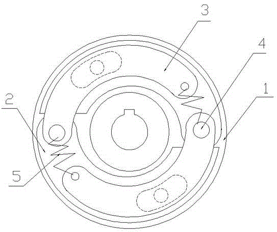
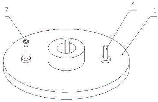
[0028] Such as Figure 1-Figure 7 A lever centrifugal clutch shown is provided with two or more positioning columns on the surface of the driving disc 1, the roots of the positioning columns 4 are all provided with steps, and the centrifugal body 2 of a group of centrifugal mechanisms One end of the centrifuge is movably socketed on the positioning column 4, and the other movable end of the centrifugal body 2 is provided with a protruding body A201 near the middle position; the corresponding special-shaped lever 3 is provided with a recessed groove A301, and the protruding body A201 enters the inside of the concave groove A301 of the special-shaped lever 3 . One end of the special-shaped lever 3 of the adjacent group of centrifugal mechanisms is movably socketed on the positioning column 4 and located on the centrifugal body 2. When the centrifugal force of the special-shaped lever 3 is greater than the tension of the tension spring 5, it passes through the side wall of the co...


PUM


Abstract

The invention discloses a lever centrifugal clutch comprising a driving disc, at least two centrifugal mechanisms and a driven disc. Each centrifugal mechanism comprises a centrifugal member, a deformed lever and a tensions spring and further comprises a positioning post. Each positioning post is movably sleeved with one end of the centrifugal member of one centrifugal mechanism and one end of the deformed lever on the adjacent centrifugal mechanism sequentially from bottom to top. Each tension spring allowing the deformed bars to return is disposed between every two adjacent deformed levers. The deformed levers are overlap-fastened to the centrifugal members by means of fitting of grooves and tongues and apply forces to the centrifugal members. As each centrifugal mechanism comprises only one positioning post, the structure of the driving disc is simplified, the manufacturing process is simplified, the production cost is lowered, the structure of the clutch is simplified, mounting and demounting are facilitated, maintenance cost is lowered, and workload is reduced for workers; shockproof washers are provided on the centrifugal members and the deformed levers, shocking of the clutch is avoided, noise is reduced, and the service life of the clutch is prolonged.

Description

technical field [0001] The invention relates to a clutch, in particular to a lever centrifugal clutch. Background technique [0002] The existing centrifugal automatic clutch has a basic structure consisting of a driving part, a centrifugal body, a driven part and a tension spring. Transmission torque (power), when the speed is lower than the set speed (starting speed), the centrifugal body is pulled back by the return spring, the centrifugal body is completely separated from the friction disc, and the contact (power) is broken. In actual use, this centrifugal clutch will be subjected to the action of the return spring all the time, and the power loss is relatively serious. To overcome the above deficiencies, reduce power loss. In addition, in some cases where the engine speed is low, such as a tiller, the tiller cannot be used normally. For this reason, I have designed a lever centrifugal clutch, which has applied for an invention patent. The name: "Lever centrifugal clu...

Claims


Application Information

Patent Timeline
IPC IPC(8): F16D43/18
Inventor 姜建中
Owner 嘉善陶庄再生资源有限公司
Why Eureka
Try Eureka