Ceramic spray drying tower

A spray drying tower and ceramic technology, which is applied in the direction of drying solid materials, drying, dryers, etc., can solve the problems of affecting the discharge speed of materials, increasing the draft of induced draft fans, and wasting energy by heat energy, so as to improve the drying effect, The effect of reducing powder particles and improving drying efficiency

Inactive Publication Date: 2015-03-25
钱达
View PDF0 Cites 3 Cited by
  • Summary
  • Abstract
  • Description
  • Claims
  • Application Information

AI Technical Summary

Problems solved by technology

[0002] At present, the spray drying tower is a common equipment used for rapid and continuous drying of wet materials. It has the advantages of continuous production, fast drying speed, convenient operation and control, and is suitable for large-scale production. The existing problems of the existing spray drying tower: In order to prevent The outside air enters the tower from the mouth of the discharge pipe to affect the drying effect. The diameter of the discharge pipe is set very small, but this will inevitably affect the discharge speed of the material and reduce the working efficiency.
[0003] Moreover, the suction force of the induced draft fan increases greatly, resulting in an increase in the negative pressure in the tower, and the exhaust air temperature is as high as 110°C to 130°C, causing a large amount of heat energy to be discharged and wasting energy. At the same time, due to the excessive negative pressure, the extracted powder particles are Many, the steam discharged after wet treatment contains a certain amount of fine powder particles, which on the one hand causes waste of raw materials and on the other hand causes harm to the atmospheric environment

Method used


Image

  • Ceramic spray drying tower

Examples


Embodiment Construction

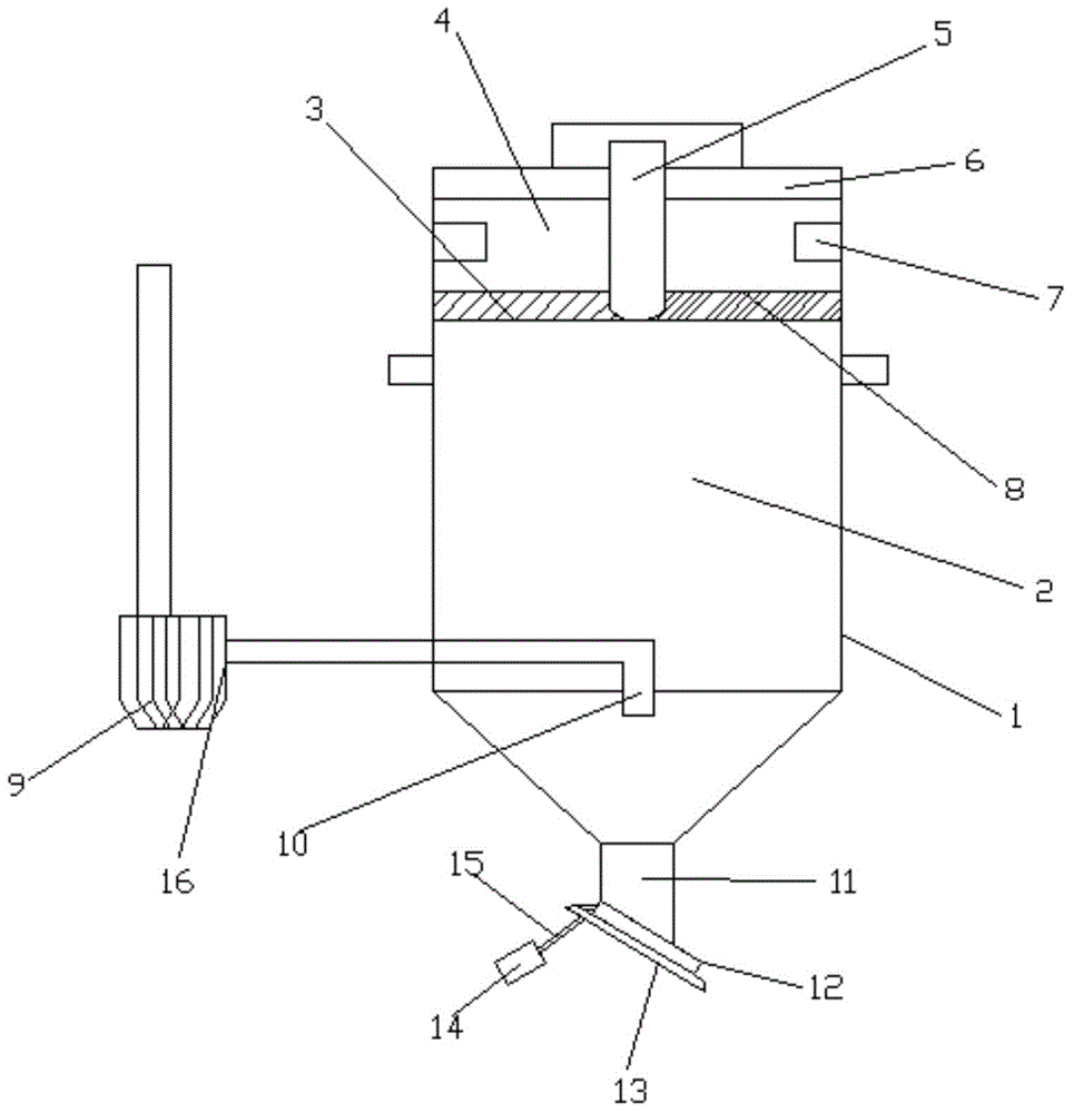
[0011] In order to further understand and recognize the structure, features and effects of the present invention, a preferred embodiment is now given, and detailed descriptions are as follows in conjunction with the accompanying drawings:

[0012] Such as figure 1 As shown, a ceramic spray drying tower described in this embodiment mainly includes a tower body 1, a discharge pipe 11 and a water atomization pipe 9, the discharge pipe 11 is arranged below the tower body 1, and above the tower body 1 A sealing cover 6 is provided, and a material sprayer 5 protruding into the tower body 1 stabilizing chamber 4 is provided in the middle, an air inlet 7 is provided on the wall of the stabilizing chamber 4, and an air hole 3 and an air inlet plate 8 are arranged below, and the air hole 3 is provided with a drying chamber 2 below, and the water atomizing pipe 9 is provided with a suction pipe 10 extending into the drying chamber 2 through the pipe body. A dust collector 16 is connected...


PUM


Abstract

The invention discloses a ceramic spray drying tower comprising a tower body, a discharge pipe and a water atomization pipe. The drying tower is characterized in that the discharge pipe is arranged under the tower body, a seal cover is arranged above the tower body, an atomizer extending into a steady-flow cavity of the tower body is arranged on the middle of the tower body, an air inlet is arranged in the wall surface of the steady-flow cavity, air holes and an air inlet plate are arranged under the steady-flow cavity, and a drying chamber is arranged under the air holes. With a moving retainer plate, the ceramic spray drying tower can prevent outside air from entering the drying tower, the pressure inside the drying tower body is decreased, the speed of material cyclone separation is increase and the drying effect and drying efficiency of materials are further improved, furthermore, the installation position of an air aspiration pipe is elevated, fewer powder particles are sucked in, and negative pressure and temperature of exhausting air are decreased. The ceramic spray drying tower is simple in structure and convenient to use.

Description

technical field [0001] The invention relates to the field of ceramic machinery, in particular to a ceramic spray drying tower. Background technique [0002] At present, the spray drying tower is a common equipment used for rapid and continuous drying of wet materials. It has the advantages of continuous production, fast drying speed, convenient operation and control, and is suitable for large-scale production. The existing problems of the existing spray drying tower: In order to prevent The outside air enters the tower from the mouth of the discharge pipe to affect the drying effect. The diameter of the discharge pipe is set very small, but this will inevitably affect the discharge speed of the material and reduce the working efficiency. [0003] Moreover, the suction force of the induced draft fan increases greatly, resulting in an increase in the negative pressure in the tower, and the exhaust air temperature is as high as 110°C to 130°C, causing a large amount of heat ene...

Claims


Application Information

Patent Timeline
Patent Type & Authority Applications(China)
IPC IPC(8): F26B17/10F26B25/00
Inventor 区其安
Owner 钱达
Why Eureka
Try Eureka