
Pseudo-random code system-based laser fuze system and target identification method thereof

A pseudo-random code and laser fuze technology, which is applied in the field of laser fuze, can solve the problems of early missile bombing, loss of combat opportunities, blind fire, etc., and achieve the effect of accurate target recognition

Inactive Publication Date: 2015-03-25
SHANGHAI DIANJI UNIV
View PDF5 Cites 18 Cited by
  • Summary
  • Abstract
  • Description
  • Claims
  • Application Information

AI Technical Summary

Problems solved by technology

[0003] At present, the research on laser fuze technology is still in its infancy, and the pulse system is generally used. Generally, a single beam is used, that is, single-quadrant detection, and the code length is relatively short, which limits the application of the fuze.
[0004] Although the laser fuze of the pulse system has excellent anti-jamming performance and other advantages, its advantages are generally obtained under the conditions of reducing the operating distance, improving the working signal-to-noise ratio, and sacrificing the instantaneous and complex signal processing capabilities. The pulse system cannot essentially solve the problem of anti-jamming, especially the problem of anti-active jamming
Working under the interference of ground and sea clutter, clouds, sandstorms, strong background light and increasingly complex photoelectric interference may cause false alarms or blockages, causing early bombing or misfiring of missiles, loss of good combat opportunities, and endangering the safety of one's own side

Method used


Image

  • Pseudo-random code system-based laser fuze system and target identification method thereof
  • Pseudo-random code system-based laser fuze system and target identification method thereof
  • Pseudo-random code system-based laser fuze system and target identification method thereof

Examples


Embodiment Construction

[0047] The embodiments of the present invention will be described below through specific examples and in conjunction with the accompanying drawings, and those skilled in the art can easily understand other advantages and effects of the present invention from the contents disclosed in this specification. The present invention can also be implemented or applied through other different specific examples, and various details in this specification can also be modified and changed based on different viewpoints and applications without departing from the spirit of the present invention.

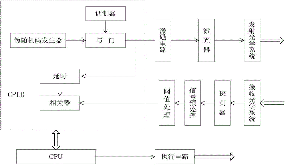
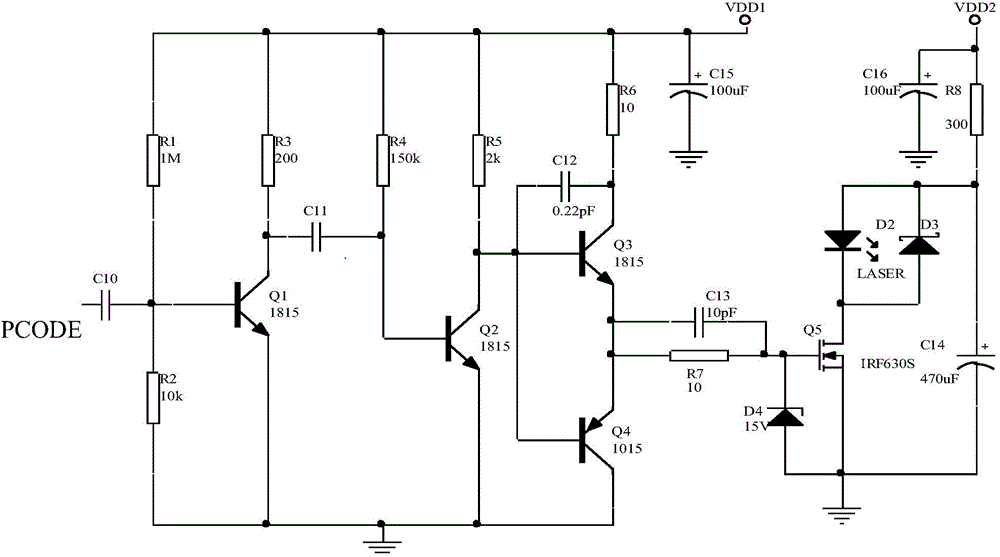
[0048] figure 1It is a system block diagram of a pseudo-random code system laser fuze system of the present invention. The present invention adopts a six-quadrant detection scheme. Six pairs of detection transceiver systems are evenly arranged along the circumferential direction of the projectile equatorial plane, with a difference of 60° from each other. Processing circuitry, transmit and receive ...


PUM


Abstract

The invention discloses a pseudo-random code system-based laser fuze system and a target identification method thereof. The laser fuze system adopts a six-quadrant detection scheme, and each pair of detection transceiver systems comprises a pseudo-random code generator, an excitation circuit, a laser, a detector, a signal processing circuit, and transmitting and receiving optical systems; the pseudo-random code generator is used for generating a pseudo-code signal with certain code element width and frequency, the pseudo-code signal is modulated to obtain a pseudo-code pulse signal meeting the requirement of pulse width of the laser, and the pseudo-code pulse signal is excited by the excitation circuit to drive the laser to transmit encoded laser pulse; finally, a laser beam irradiates to a target after being collimated or extended by a transmitting optical system, and the optical energy reflected from the target is received by the receiving optical system; meanwhile, the filtering of a filter and the focusing of the light beam are completed, and after the detector completes the photoelectric conversion and the signal preprocessing of the signal processing circuit, an echo pseudo-random coded signal is obtained after threshold comparison.

Description

technical field [0001] The invention relates to the field of laser fuze, in particular to a laser fuze system of pseudo-random code system and a target identification method thereof. Background technique [0002] Laser technology is one of the high-tech technologies developed in the 1960s. Over the past 40 years, laser technology has achieved rapid development. Because laser has a series of excellent characteristics such as sharp directionality, high brightness, monochromaticity and good coherence, it has been widely used in weapon systems, and laser fuze is one of them. At present, laser fuzes have been widely used in anti-tank missiles, surface-to-air missiles, air-to-surface missiles, air-to-air missiles, terminal ballistic correction shells, mortar shells and other precision strike weapons and smart ammunition. In recent years, laser fuzes have been widely used in anti-radiation attack weapons. Anti-radiation weapons are tactical weapons specially used to attack electr...

Claims


Application Information

Patent Timeline
IPC IPC(8): F42C13/02
Inventor 胡秀娟计春雷黎明
Owner SHANGHAI DIANJI UNIV
Learn More