
Handheld target detector and detection method and trajectory calculation method thereof

A detector and target technology, applied in the field of target detector and its detection, can solve the problems of inconvenient portability, slow positioning speed, and short positioning target distance for soldiers, achieve simple, reliable and fast operation, and reduce the total volume of equipment , The effect of reducing the total cost of equipment

Active Publication Date: 2015-03-25
扬州天目光电科技有限公司 +1
View PDF7 Cites 19 Cited by
  • Summary
  • Abstract
  • Description
  • Claims
  • Application Information

AI Technical Summary

Problems solved by technology

The disadvantage of these equipments is that the functions are single and scattered, the measured target coordinates are often one-dimensional or two-dimensional, and the three-dimensional coordinates of the target in the earth coordinate system cannot be measured, the positioning accuracy is not high, and the ranging frequency is low. The positioning speed is slow, the distance of the positioning target is short, it cannot quickly locate the moving target in real time, and it does not have the function of directly communicating with the weapon platform and the command personnel
Due to the variety of equipment, it is inconvenient for soldiers to carry and the cost of equipment is high

Method used


Image

  • Handheld target detector and detection method and trajectory calculation method thereof
  • Handheld target detector and detection method and trajectory calculation method thereof
  • Handheld target detector and detection method and trajectory calculation method thereof

Examples


Embodiment Construction

[0054] The specific implementation manners of the present invention will be further described in detail below in conjunction with the accompanying drawings and embodiments. The following examples are used to illustrate the present invention, but are not intended to limit the scope of the present invention.

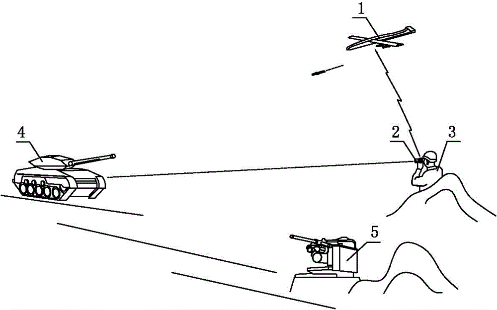
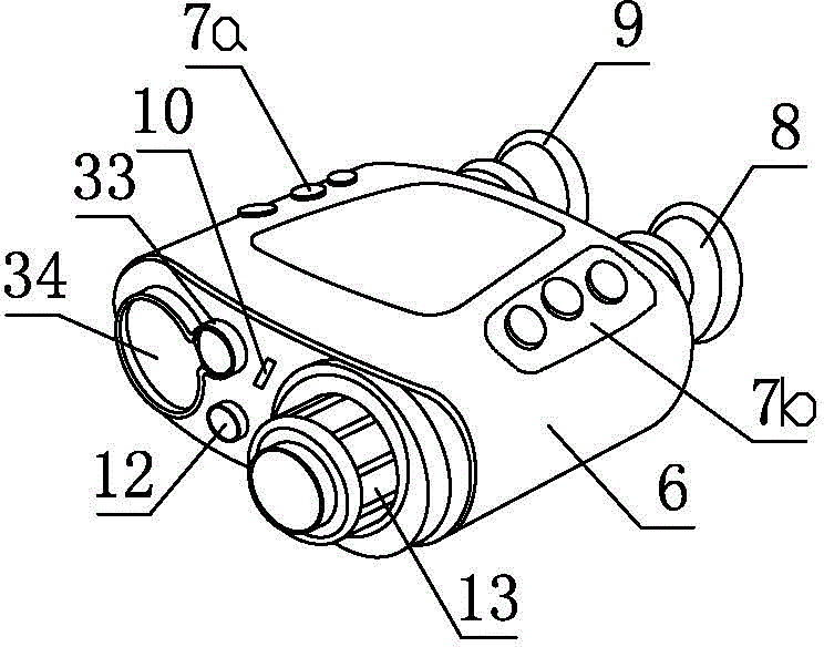
[0055] figure 1 It is a schematic diagram of the use of the handheld target detector of the present invention. The soldier 3 carries the handheld target detector 2, goes deep into the front position, hides behind the woods or mounds, and conducts space reconnaissance on the enemy target 4. Soldiers 3 first determine their own earth coordinates with the handheld target detector 2, then aim at the target 4, measure the distance of the target 4, measure the azimuth angle of the target 4, measure the inclination angle of the handheld target detector 2 when aiming at the target, and then use Measure the data to calculate the position and orientation of the target. Once the co...


PUM


Abstract

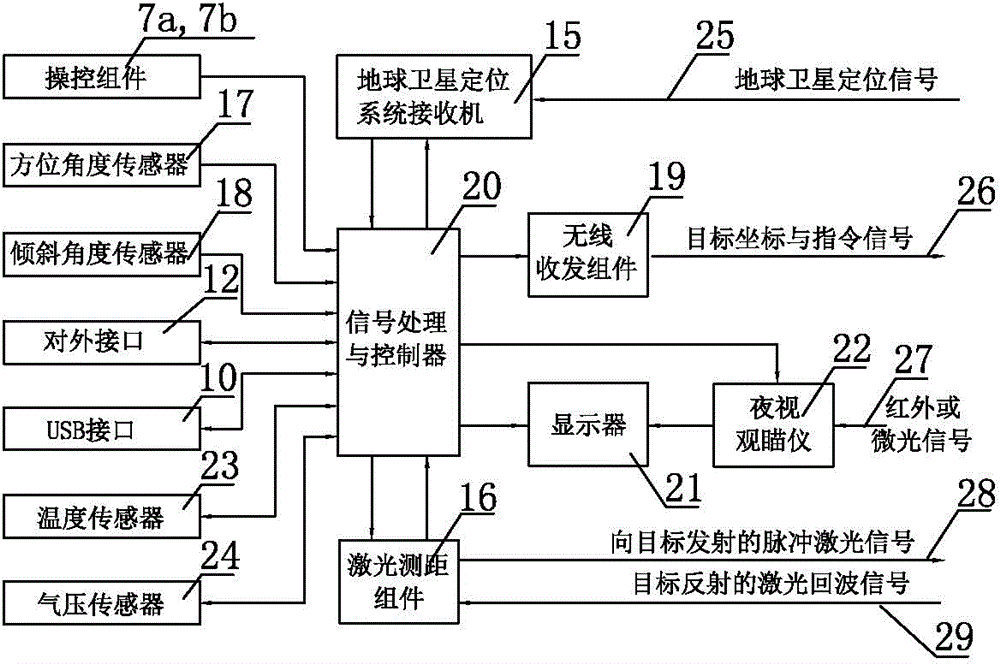
The invention discloses a handheld target detector in the field of target measurement and locating. According to the handheld target detector, with comprehensive application of multiple techniques of laser ranging, angle measurement of a digital compass and an inclination sensor, locating of an earth locating system and the like, three-dimensional locating of a static or moving object can be rapidly performed with high precision; temperature, air pressure sensor and trajectory parameters are integrated, and the loading amount can be provided for conventional weapons; with a wireless or wired networking function, target locating information, a weapon platform control instruction and a damage assessment instruction can be sent in real time; working procedures of target data acquisition and information transmission are started in a key manner, and thus the operation is simple, reliable and rapid; as a target locating procedure without distance value is designed, a target can be located precisely under the conditions that the distance of the target is overlong, the reflectivity of the target is low and the weather visibility is low, and the handheld target detector can be applied to various military environments.

Description

technical field [0001] The invention relates to target coordinate measuring equipment, in particular to a target detector and a detection method thereof. Background technique [0002] Modern warfare is gradually changing to an unmanned beyond visual range mode. The battlefield is fully moved forward. The role of infantry is no longer to fight at close range. Evaluation of the damage to the target that has been attacked. In order to adapt to the new combat mode of future wars and meet the needs of precise strike and fixed-point clearance, the troops need an instrument that can quickly and accurately measure the coordinates of the target. [0003] In anti-terrorism operations and border crossings, ground troops penetrate deep into the enemy's theater of operations, and often adopt long-distance rear attacks and air support to protect ground troops. However, when the ground forces are intertwined with enemy personnel, or there are civilians around the enemy's position, in ord...

Claims


Application Information

Patent Timeline
IPC IPC(8): G01C21/00G01S19/19G01C3/04
CPCG01C1/00G01C9/00G01C17/02G01S17/08G01S19/18G01S19/42
Inventor 郁麒麟其他发明人请求不公开姓名
Owner 扬州天目光电科技有限公司
Learn More