

Simple detection method of differential pressure device
A technology of differential pressure device and detection method, which is applied to the pressure difference measurement between multiple valves, the detection of fluid flow by measuring the pressure difference, the direction of the measurement device, etc., which can solve the problems of complicated calculation and achieve high efficiency and simple measurement. Effect
Active Publication Date: 2015-03-25
STATE GRID CORP OF CHINA +1
View PDF5 Cites 8 Cited by
- Summary
- Abstract
- Description
- Claims
- Application Information
AI Technical Summary
Problems solved by technology
[0008] The calculation of each type of differential pressure device requires 4 programs, and the three types of differential pressure devices require 12 programs, and the calculation is very cumbersome
Method used
View moreImage
Smart ImageViewing Examples

Examples
Embodiment
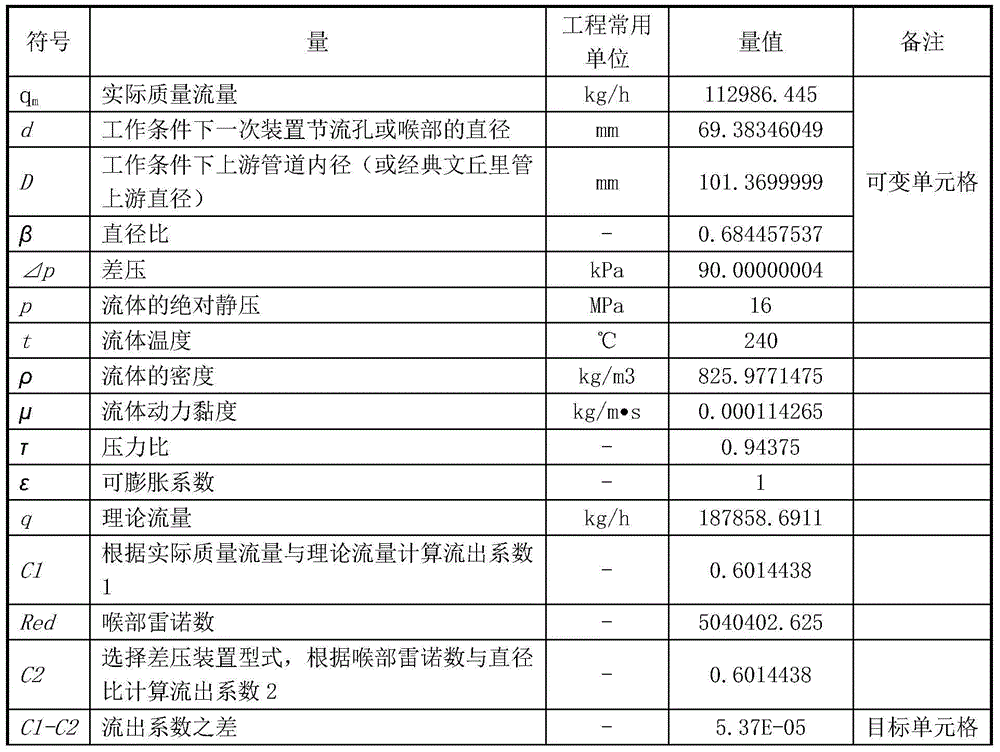
[0052] In order to further describe in detail, an actual calculation is performed below in conjunction with an embodiment, where the throttling member is an orifice plate and the measured medium is water. Specifically, follow steps 1 to 4, and the results are shown in the table below:
[0053] Table I
[0054]
Login to View More PUM
 Abstract
The invention discloses a simple detection method of a differential pressure device. The simple detection method includes the steps that EXCEL table cells are filled with the practical mass flow q<m> of the differential pressure device, the inner diameter D of an upstream pipe under the working condition, the diameter d of a throttle hole or a throat part of a primary device under the working condition, the differential pressure deltap and the diameter ratio beta from top to bottom; initial values are assigned to quantities required to be solved, and other quantities are obtained through measurement by a measurement device; the fluid density and the dynamic viscosity are determined according to characteristic parameters, namely the pressure and the temperature, of fluid of the differential pressure device; the discharge coefficient C1 and the discharge coefficient C2 are calculated; the difference value between the discharge coefficient C1 and the discharge coefficient C2 is calculated to serve as a target table cell, a target value is zero, when a certain value is needed to be solved, the table cell where the certain value is located is selected to be a variable table cell, a determining button is clicked, and a value in the variable table cell is the result of the quantity needing to be solved after calculation is completed. The simple detection method is rapid, simple and convenient to detect.
Description
technical field [0001] The invention relates to a simple detection method of a differential pressure device. Background technique [0002] The differential pressure device refers to the orifice plate, nozzle and Venturi nozzle referred to in the national standard "GB / T2624.1-2006 / ISO5167-1:2003 Measuring the Fluid Flow of a Full Pipe with a Differential Pressure Device Installed in a Circular Section Pipeline" ,Venturi tube. Its measurement principle is based on the installation of primary devices (such as orifice plates, nozzles, and Venturi tubes) in pipelines filled with fluid. A static pressure differential is created between the upstream side of the device and the throat or downstream side of the device once installed. Based on the measured value of this differential pressure and the characteristics of the flowing fluid and the environment in which the device is used, the flow rate can be determined assuming that the device is geometrically similar to the calibrated o...
Claims
Login to View More Application Information
Patent Timeline
 Patent Type & AuthorityApplications(China)
IPC IPC(8): G01L13/02G01F1/34G01F25/00
Inventor车永强吕海祯张虎杨建柱
OwnerSTATE GRID CORP OF CHINA