

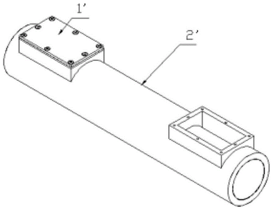
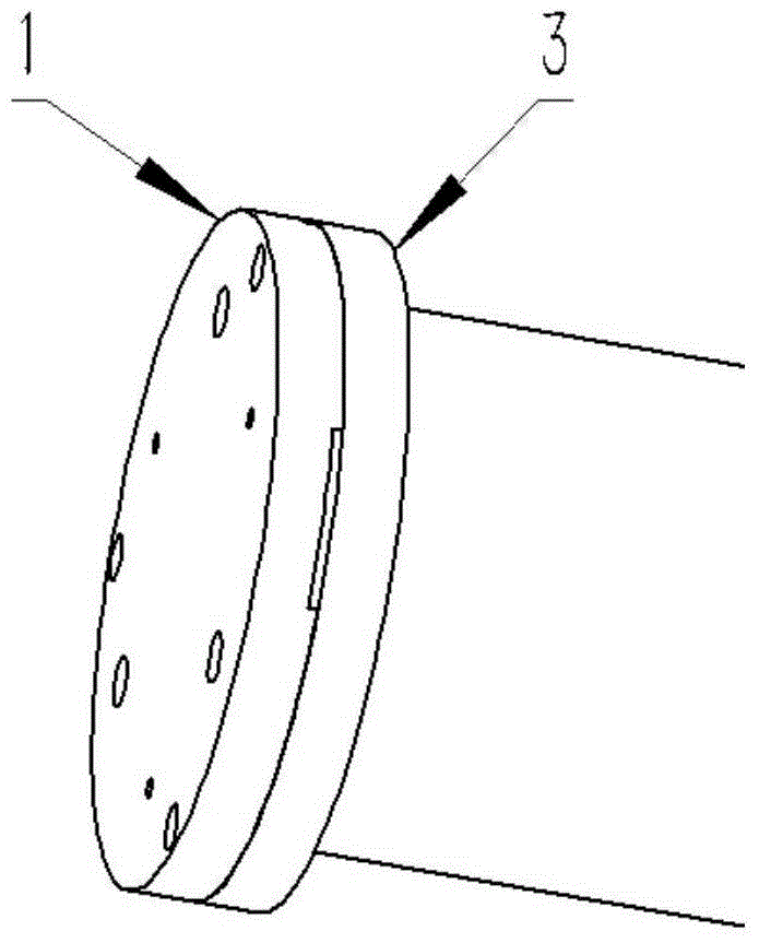
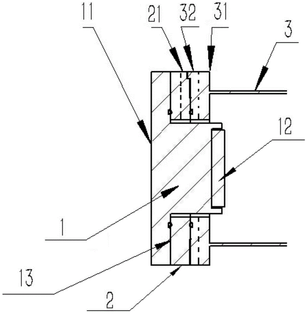
Sample chamber of sample analysis device
A technology of sample analysis and sample chamber, which is applied in the direction of measuring devices, analyzing materials, and material analysis through optical means, can solve the problems of increasing maintenance difficulty and workload, limited space, and increasing processing costs, and achieves installation and maintenance. High maintenance and reset accuracy, convenient cleaning, and consistent results
- Summary
- Abstract
- Description
- Claims
- Application Information
AI Technical Summary
Problems solved by technology
Method used
Image

Examples
Embodiment Construction
[0036] The optical components in the sample analyzer are easily contaminated by impurities in the sample during use. The existing cleaning method is to clean the optical components on the basis of disassembly and by opening a maintenance window on the wall of the sample chamber, but this method Due to the space and angle limitations of the maintenance window, there are dead angles for observation and cleaning, and the cleaning of the optical components is not thorough enough; if the optical components are disassembled and cleaned, there is no guarantee that the optical components can return to their original positions without the operation of professionals. In view of the above problems, the present invention discloses a sample chamber of a sample analysis device that can thoroughly clean the optical element and allow the optical element to be accurately assembled.
[0037] The technical solutions of the present invention will be further described in detail below through embodi...
PUM
 Abstract
Description
Claims
Application Information