Triangular looped network ranging distance continuation method

A triangular ring and range technology, which is applied in the field of triangular ring network ranging extension, can solve the problems of increased cost of ranging, unavoidable, and failure of fault ranging, and achieves the effect of accurate and reliable ranging results and simple principles

Inactive Publication Date: 2015-03-25
CHUXIONG POWER SUPPLY BUREAU OF YUNNAN POWER GRID CO LTD +1
View PDF5 Cites 3 Cited by
  • Summary
  • Abstract
  • Description
  • Claims
  • Application Information

AI Technical Summary

Problems solved by technology

The traditional traveling wave distance measuring method can only measure the distance of the line monitored by the traveling wave distance measuring device, but cannot perform fault distance measurement on the line without the traveling wave distance measuring device
For a triangular ring network composed of transmission lines between th

Method used


Image

  • Triangular looped network ranging distance continuation method
  • Triangular looped network ranging distance continuation method
  • Triangular looped network ranging distance continuation method

Examples


Embodiment 1

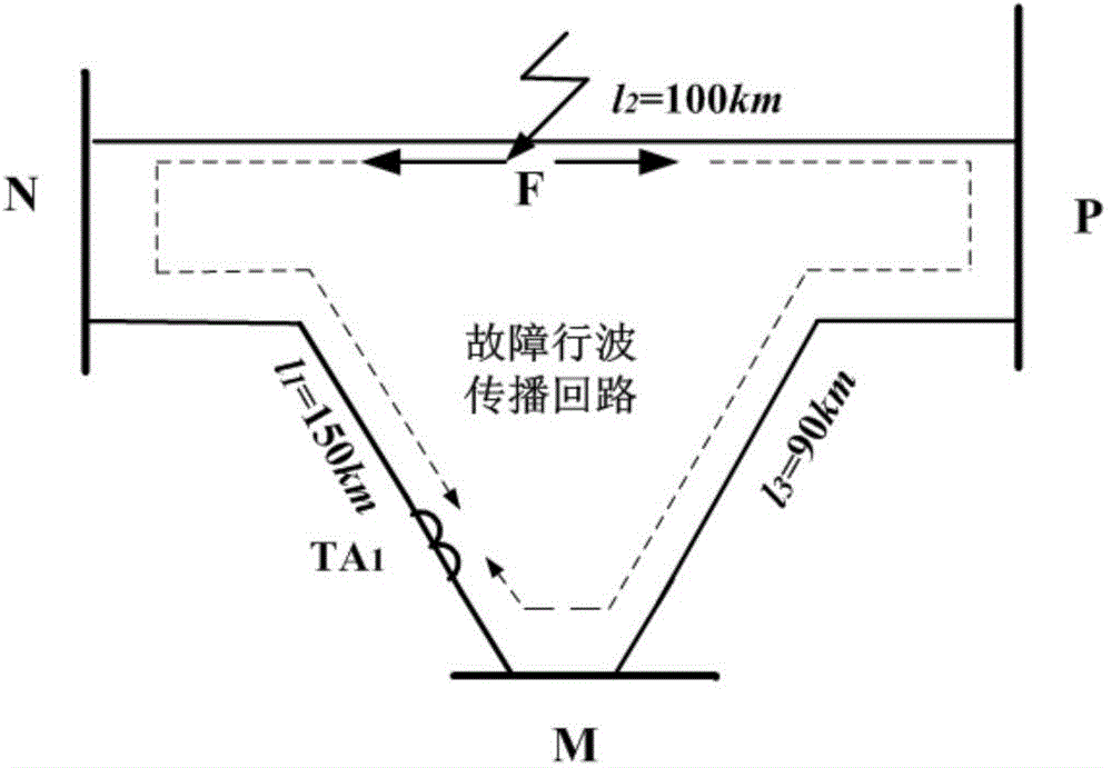
[0031] Such as figure 1 In the triangular ring network shown, the three busbars are respectively M, N, and P, and the lengths of each line are: l 1 = 150km, l 2 = 100km, l 3 =90km. Assumed line l 2 A phase-to-ground fault occurs 40km away from the N terminal of the busbar. The initial angle of the fault is 90°, the transition resistance is 10Ω, and the sampling rate is 1MHz.

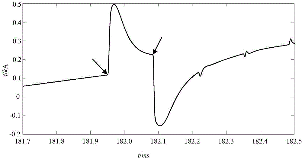
[0032] according to figure 2 The time corresponding to the first wave head of the two faults is found from the current traveling wave diagram shown as t 1 = 0.182081s,t 2 =0.181949s; find the first wave head time difference Δt=t 1 -t 2 =0.000132s, v is taken as the empirical wave velocity, and its magnitude is 2.98×10 8 m / s; finally use the formula (2) to calculate the fault distance x=(v·Δt-l 1 +l 2 +l 3 ) / 2=39.668km.

Embodiment 2

[0034] Such as figure 1 In the triangular ring network shown, the three busbars are respectively M, N, and P, and the lengths of each line are: l 1 = 150km, l 2 = 100km, l 3 =90km. Assumed line l 2 A phase-to-ground fault occurs at a distance of 55km from the N terminal of the busbar. The initial fault angle is 60°, the transition resistance is 10Ω, and the sampling rate is 1MHz.

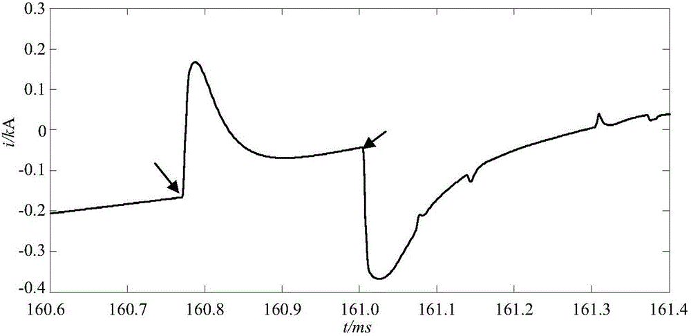
[0035] according to image 3 Find the time t corresponding to the first wave head of the two faults from the current traveling wave diagram shown 1 = 0.161009s,t 2 =0.160770s; find the first wave head time difference Δt=t 1 -t 2 =0.000239s, v is taken as the empirical wave velocity, and its size is 2.98×10 8 m / s; finally use the formula (2) to calculate the fault distance x=(v·Δt-l 1 +l 2 +l 3 ) / 2=55.611 km.

Embodiment 3

[0037] Such as figure 1 In the triangular ring network shown, the three busbars are respectively M, N, and P, and the lengths of each line are: l 1 = 150km, l 2 = 100km, l 3 =90km. Assumed line l 2 A phase-to-ground fault occurs 70km away from the N terminal of the busbar. The initial fault angle is 60°, the transition resistance is 10Ω, and the sampling rate is 1MHz.

[0038] according to Figure 4 Find the time t corresponding to the first wave head of the two faults from the current traveling wave diagram shown 1 = 0.161052s,t 2 =0.160715s; find the first wave head time difference Δt=t 1 -t 2 =0.000337s, v is taken as the empirical wave velocity, and its magnitude is 2.98×10 8 m / s; finally use the formula (2) to calculate the fault distance x=(v·Δt-l 1 +l 2 +l 3 ) / 2=70.213km.


PUM

PropertyMeasurementUnit
Sampling rateaaaaaaaaaa

Abstract

The invention relates to a triangular looped network ranging distance continuation method and belongs to the technical field of power system relay protection. The method includes the steps that according to a triangular looped network composed of power transmission lines among three transformer substations, a travelling wave ranging device is arranged only in the transformer substation connected with a busbar M, and the lines l1 and l3 which are adjacent to each other are monitored. After a fault happens in the power transmission line l2, which is not monitored by the travelling wave ranging device, in the looped network, initial fault travelling waves reach busbars N and P at the two ends of the fault line and are transmitted to the perfect lines in the looped network through the busbars, current travelling waves of a measuring end TA1 of the perfect line l1 are acquired through the travelling wave ranging device, the time for the initial fault travelling waves to reach the TA1 through the perfect line l1 and the time for the initial fault travelling waves to reach the TA1 through the perfect line l3 are respectively recorded, then, the time difference delta t is calculated, and finally, the fault distance x is calculated according to the overall length of all the lines of the triangular looped network and experimental wave speed. Theoretical analysis and a simulation result show that the method is not affected by fault instantaneity, fault transition resistance changes and other factors, and a ranging result is accurate and reliable.

Description

technical field [0001] The invention relates to a method for extending the ranging range of a triangular ring network, which belongs to the technical field of electric power system relay protection. Background technique [0002] Transmission lines have long distances and large spans, and various faults occur from time to time. Quickly and accurately determining the location of line faults can help reduce the burden of on-site operation and maintenance personnel, shorten the time for fault repair, and reduce the loss of system power outages. Ensure the stable operation of the power system. [0003] As one of the fault location methods, the traveling wave method uses the propagation time of the fault traveling wave between the bus and the fault point to measure the fault distance. Its distance measurement accuracy is high and its application range is wide. The traditional traveling wave distance measuring method can only measure the distance of the line monitored by the trav...

Claims


Application Information

Patent Timeline
IPC IPC(8): G01R31/08
Inventor 纪思杨桥伟朱净松施辉选李起荣李天权冯鹏杨明涅谢德琴徐赛梅束洪春余多白冰
Owner CHUXIONG POWER SUPPLY BUREAU OF YUNNAN POWER GRID CO LTD
Why Eureka
Try Eureka