System and method for simultaneously measuring lengths of two optical fibers

An optical fiber length and optical fiber technology, which is applied in the field of systems that measure the length of two optical fibers at the same time to achieve the effect of short measurement time.

Inactive Publication Date: 2015-03-25
SHANGHAI UNIV
View PDF5 Cites 7 Cited by
  • Summary
  • Abstract
  • Description
  • Claims
  • Application Information

AI Technical Summary

Problems solved by technology

The optical fiber ring laser method based on the semiconductor optical amplifier can measure the length of the optical fiber in the access ring, the measurement is simple, fast, and there is no dead zone, but all these methods can only obtain the length of one optical fiber at a time

Method used


Image

  • System and method for simultaneously measuring lengths of two optical fibers
  • System and method for simultaneously measuring lengths of two optical fibers
  • System and method for simultaneously measuring lengths of two optical fibers

Examples


Embodiment 1

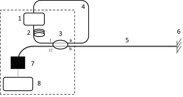
[0029] Such as figure 1 As shown, a system for simultaneously measuring the length of two optical fibers includes an optical amplifier 1, a polarization controller 2, an output coupler 3, a first standard single-mode fiber to be tested 4, a second standard single-mode fiber to be tested 5, and a reflection Mirror 6, photodetector 7 and data acquisition and processing system 8; Described comprises optical amplifier 1, polarization controller 2, output coupler 3 and the first standard single-mode optical fiber 4 to be tested and is sequentially connected with standard single-mode optical fiber jumper , constitute a fiber ring laser, the polarization controller 2 is connected to the I port of the output coupler 3, and the first standard single-mode fiber 4 to be tested is connected to the a port of the output coupler 3; the b port of the output coupler 3 The second standard single-mode optical fiber 5 to be tested is externally connected, and the other end of the second standard...

Embodiment 2

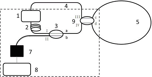
[0031] This embodiment is basically the same as Embodiment 1, and the special features are as follows: figure 2 Shown, also comprise the coupler 9 of the 50 / 50 of a 2X2, the III port of described coupler 9 connects the first to-be-tested standard single-mode optical fiber 4, and the IV port connects the a port of output coupler 3, is comprised by described The optical amplifier 1, the polarization controller 2, the output coupler 3, the first standard single-mode fiber to be tested 4 and the coupler 9 constitute a fiber ring laser; the c and d ports of the coupler 9 are externally connected to the second standard single-mode fiber to be tested The optical fiber 5 forms a passive reflection loop; the b port of the output coupler 3 is not used anymore.

Embodiment 3

[0033]In this embodiment, the optical amplifier 1 selects the SOA module (SOA-S-C-14-FCA) of British CIP Technologies Company, the polarization controller 2 adopts the optical fiber extruder (PLC-001) of General Photonics Company, and the output coupler 3 adopts The 2X2 coupler produced by Shanghai Hanyu Optical Fiber Communication Technology Co., Ltd. has a splitting ratio of 50:50. Reflector 6 is a reflector formed by self-made optical fiber end face coating. Photodetector 7 is a PIN-TIA detector produced by Shenzhen Feitong Company. The data acquisition and processing system 8 consists of an ordinary microcomputer and a PicoScope 5203 digital oscilloscope from PICO Company in the United Kingdom. The oscilloscope transmits the collected data to the computer, and uses Matlab software to program and calculate the autocorrelation function and Fourier transform of the collected chaotic data. All optical fibers adopt G.652 standard single-mode optical fiber. The length of the f...


PUM


Abstract

The invention discloses a system and method for simultaneously measuring the lengths of two optical fibers. The system comprises an optical fiber ring laser, a second standard single-mode optical fiber to be tested, a reflector or a coupler, a photoelectric detector and a data collecting and processing system, wherein the optical fiber ring laser is formed by sequentially connecting a semiconductor optical amplifier or an erbium-doped optical fiber optical amplifier, a polarization controller, an output coupler and a first standard single-mode optical fiber to be tested through an optical fiber patch cord. One end of the second optical fiber to be tested is connected with the output coupler, and the other end of the second optical fiber to be tested is connected with the reflector; or the two ends of the second optical fiber to be tested are connected with two ports in one side of the 50/50 coupler, and the optical fiber ring laser is connected in two ports in the other side of the coupler. Optical signals output by the output coupler are converted into electric signals through the photoelectric detector, and the electric signals enter the data collecting and processing system. The time interval of two stages of adjacent correlation peaks or the frequency interval of two stages of adjacent harmonic peaks are obtained by calculating the autocorrelation function of chaos waveform data output by the system or through the Fourier transform, and therefore the length of the first optical fiber to be tested and the length of the second optical fiber to be tested are obtained through conversion.

Description

technical field [0001] The invention relates to a system and method for simultaneously measuring the length of two optical fibers. Background technique [0002] It is necessary to measure the length of optical fiber in both scientific experiments and engineering practice. Several existing typical methods for measuring the length of optical fibers include optical time domain reflectometer (OTDR), optical frequency domain reflectometer (OFDR) and optical low coherence reflectometer (OLCR). However, the measurement accuracy of OTDR is low, and there are inevitable inherent errors, and it cannot measure the length of short optical fibers. OFDR and OLCR equipment are expensive and have low stability. Moreover, the measurable range of OLCR is very limited, only a few centimeters long. Other optical fiber length measurement methods, such as the all-fiber interferometer method, have no dead zone in the measurement, but the measurement accuracy is low. The mode-locked fiber laser...

Claims


Application Information

Patent Timeline
Patent Type & Authority Applications(China)
IPC IPC(8): G01S11/12
CPCG01S11/12
Inventor 方捻王陆唐黄肇明
Owner SHANGHAI UNIV
Why Eureka
Try Eureka