Water resistance rowing machine

A rowing machine and water resistance technology, applied in simulators, instruments, space navigation equipment, etc., can solve the problems of increasing consumption, increasing the burden on rowers, and laboriousness, achieving low resistance, improving service life, and reducing space for use Effect

Active Publication Date: 2015-03-25
安徽立查信息科技有限公司
View PDF8 Cites 11 Cited by
  • Summary
  • Abstract
  • Description
  • Claims
  • Application Information

AI Technical Summary

Problems solved by technology

Its disadvantages are: rowing is laborious, the blades need to be actively reset, which increases the consumption of rowing, increases the burden on the rower, and cannot simulate the best rowing state

Method used


Image

  • Water resistance rowing machine
  • Water resistance rowing machine
  • Water resistance rowing machine

Examples


Embodiment 1

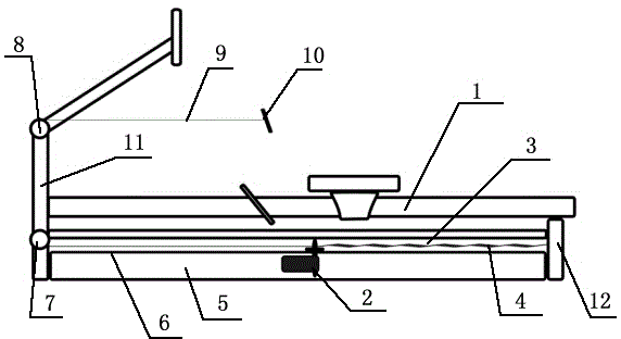
[0022] Embodiment 1: with reference to attached Figure 1-2 , a water resistance rowing machine, comprising a hull 1, paddles 13 and rails 6, a pedal and a seat are arranged in the hull 1, a cavity 3 is arranged at the bottom of the hull 1, and a pool 5 is arranged outside the cavity 3 at the bottom of the hull 1, The bottom surface of the cavity 3 is provided with a track 6 that communicates with the outside of the cavity 3 and the bottom of the hull 1. A sliding device 2 is arranged in the track 6, and the bottom of the sliding device 2 passes through the track 6 and is immersed in the pool 5. The upper part of the sliding device 2 Located in the cavity 3, one end of the upper part of the sliding device 2 is connected to the elastic rope 4, and the other end of the elastic rope 4 is connected to the hull 1, and the other end of the upper part of the sliding device 2 in the cavity 3 is connected to the rope 9, and the other end of the rope 9 One end walks around the fixed pul...

Embodiment 2

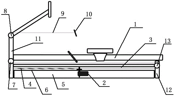
[0024] Embodiment 2: with reference to attached figure 1 , a water resistance rowing machine, comprising a hull 1, paddles 13 and rails 6, a pedal and a seat are arranged in the hull 1, a cavity 3 is arranged at the bottom of the hull 1, and a pool 5 is arranged outside the cavity 3 at the bottom of the hull 1, The bottom surface of the cavity 3 is provided with a track 6 that communicates with the outside of the cavity 3 and the bottom of the hull 1. A sliding device 2 is arranged in the track 6, and the bottom of the sliding device 2 passes through the track 6 and is immersed in the pool 5. The upper part of the sliding device 2 Located in the cavity 3, one end of the upper part of the sliding device 2 is connected to the elastic rope 4, and the other end of the elastic rope 4 is connected to the rear column 12 of the hull 1, and the other end of the upper part of the sliding device 2 in the cavity 3 is connected to the rope 9, and the other end of the elastic rope 4 is conne...

Embodiment 3

[0028] Embodiment 3: with reference to attached figure 2 , a water resistance rowing machine, comprising a hull 1, paddles 13 and rails 6, a pedal and a seat are arranged in the hull 1, a cavity 3 is arranged at the bottom of the hull 1, and a pool 5 is arranged outside the cavity 3 at the bottom of the hull 1, The bottom surface of the cavity 3 is a track 6 connecting the cavity 3 and the bottom of the hull 1. A slide device 2 is arranged in the track 6, and the lower part of the slide device 2 passes through the track 6 and is submerged in the pool 5. The top of the slide device 2 is located at In the cavity 3, one end of the upper part of the sliding device 2 is connected to the elastic rope 4, and the other end of the elastic rope 4 is connected to the front column 11 of the hull 1, and the other end of the upper part of the sliding device 2 in the cavity 3 is connected to the rope 9, and the other end of the rope 9 Go around two fixed pulleys 7,8 on the front column 11 o...


PUM


Abstract

The invention provides a water resistance rowing machine. A cavity is formed in the bottom of a hull. A track through which the cavity is communicated with the exterior of the bottom of the hull is arranged on the bottom surface of the cavity. One end of a sliding device penetrates through the track, and the sliding device is arranged in the track. One end of the part, located in the cavity, of the sliding device is connected with an elastic rope, and the other end of the elastic rope is connected with the hull. The other end of the part, located in the cavity, of the sliding device is connected with a rope, and the other end of the rope is connected with a handle. Paddles are arranged at the left end and the right end of the part, located outside the hull, of the sliding device. The water resistance rowing machine has the advantages that the paddles can reset automatically, so that labor is saved; the paddles can switch states through resistance when resetting, so that resistance on the paddles is small when the paddles reset, and the service life of the elastic rope is prolonged.

Description

technical field [0001] The invention relates to a water-resistance rowing machine, in particular to a water-resistance rowing machine whose blades can be automatically reset, the blades receive little resistance during the resetting process, simulate the best rowing scene, and switch between two simulation modes. Background technique [0002] An existing rowing machine includes a hull and a rudder. The hull is composed of a hull frame, a hoop, a floating body and a panel. The lower end is connected, the two ends of the herringbone and the two ends of the T shape are respectively connected with a hoop, and the four hoops fix the two floating bodies on both sides of the hull frame. The rudder plate is used to connect the rudder. The rudder is composed of a base, a front head pipe, a handle and a main part of the rudder. The main part of the rudder is that the lower part of the rudder can be rotatably connected to two blades, and the backer seat is fixedly connected to the ...

Claims


Application Information

Patent Timeline
Patent Type & Authority Applications(China)
IPC IPC(8): G09B9/00
CPCG09B9/00
Inventor 刘知迪
Owner 安徽立查信息科技有限公司
Why Eureka
Try Eureka