Power capacitors with good heat dissipation performance

A technology for power capacitors and heat dissipation performance, applied in capacitors, fixed capacitors, multiple fixed capacitors, etc., can solve the problems of limited overcurrent capability of capacitor cores, increased heat generation, and reduced capacitor service life, to overcome the creepage distance. The effect of shortening, increasing the heat dissipation area, and increasing the flow cross section

Active Publication Date: 2017-06-20
ANHUI TONGFENG ELECTRONICS
View PDF6 Cites 0 Cited by
  • Summary
  • Abstract
  • Description
  • Claims
  • Application Information

AI Technical Summary

Problems solved by technology

If the heat cannot be dissipated effectively and timely, it will greatly reduce the service life of the capacitor, and even affect the normal use of the capacitor.
[0003] In addition, if the over-current capability of the lead-out copper strip inside the capacitor is small, the uneven current distribution will make the local current too large, and the over-current capability of a single capacitor core is limited. damage, resulting in the capacitor not being able to work normally
[0004] For high-power power capacitors with cylindrical capacitor cores, since the capacitor cores are stacked up and down, the position of each core on the core group is inconsistent, and the current of each core is superimposed on the upper part when passing through the lead-out copper strip. , so that the current distribution on the lead-out copper strip is uneven, that is, the current density of the lower part of the lead-out copper strip is small and the upper part of the current density is large, resulting in excessive local current and increased calorific value, resulting in poor local heat dissipation, resulting in heat dissipation problems. Long-term operation will also cause damage to the capacitor, resulting in the capacitor not being able to work normally

Method used


Image

  • Power capacitors with good heat dissipation performance
  • Power capacitors with good heat dissipation performance

Examples


Embodiment Construction

[0014] The technical solutions in the embodiments of the present invention are clearly and completely described below in conjunction with the accompanying drawings. Apparently, the described embodiments are only some of the embodiments of the present invention, but not all of them. Based on the embodiments of the present invention, all other embodiments obtained by persons of ordinary skill in the art without making creative efforts belong to the protection scope of the present invention.

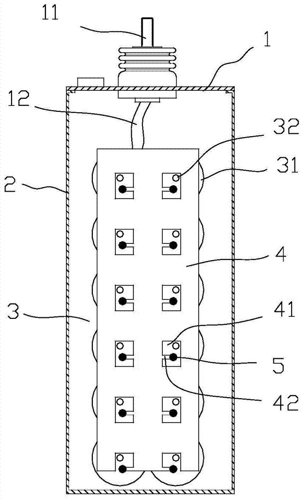
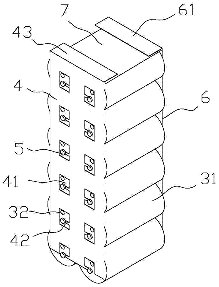
[0015] Such as figure 1 As shown, the present invention includes a cover plate assembly 1 , a casing 2 and a capacitor core group 3 fixed in the casing 2 . One or more capacitor core groups 3 can be arranged side by side, and the outside of each capacitor core group 3 is wrapped with an insulating film and placed in the casing 2, and the insulating film is placed on the figure 1 is not drawn in. The positive and negative electrodes of the capacitor core group 3 are electrically connected...


PUM


Abstract

The invention relates to a power capacitor with good heat dissipation performance, which includes a cover plate assembly, a casing and a capacitor core group. The capacitor core group is formed by superimposing several cylindrical capacitor cores, and the lead-out copper strip is arranged on the gold-sprayed surface of the capacitor core group. , the coverage area on both sides of the lead-out copper strip extends at least to the central area of ​​the gold-sprayed surface of the capacitor core located on both sides of the capacitor core group, and the lead-out copper strip has a through hole or an opening in the center of the gold-sprayed surface of each capacitor core A groove on one side of the lead-out copper strip has elastic fins extending into the through hole or groove for electrical connection with the gold-sprayed surface by welding. By enlarging the width of the lead-out copper strip, the current can pass through evenly and the calorific value can be reduced. Moreover, the area of ​​the lead-out copper strip is also doubled, and the heat dissipation performance is significantly enhanced.

Description

technical field [0001] The invention relates to a power capacitor, in particular to a power capacitor with good heat dissipation performance. Background technique [0002] When the capacitor is in normal operation, due to its own loss, the current will generate heat when it passes through the capacitor core, copper strip and solder joints and other connecting parts. If the heat cannot be dissipated effectively and timely, it will greatly reduce the service life of the capacitor, and even affect the normal use of the capacitor. [0003] In addition, if the over-current capacity of the lead-out copper strip inside the capacitor is small, the uneven current distribution will make the local current too large, and the over-current capacity of a single capacitor core is limited. Damage, resulting in the capacitor can not be used normally. [0004] For high-power power capacitors with cylindrical capacitor cores, since the capacitor cores are stacked up and down, the position of ...

Claims


Application Information

Patent Timeline
Patent Type & Authority Patents(China)
IPC IPC(8): H01G4/38H01G4/248H01G4/224
Inventor 储松潮潘毓娴张进汪威刘殿明
Owner ANHUI TONGFENG ELECTRONICS
Why Eureka
Try Eureka