
Fuel cell interior humidity-current density distribution measurement male tab

A current density, fuel cell technology, applied in fuel cells, fuel cell additives, measuring devices, etc., can solve the problems of high cost, complicated process, complicated production, etc., and achieve convenient production, simple device structure, and wide application range. Effect

Active Publication Date: 2015-03-25
BEIJING UNIV OF TECH
View PDF6 Cites 4 Cited by
  • Summary
  • Abstract
  • Description
  • Claims
  • Application Information

AI Technical Summary

Problems solved by technology

[0004] The methods for measuring current density include sub-cell method, membrane electrode segmentation method, magnetic ring group method, etc. Most of them need to modify the structure of the fuel cell, which is complicated to manufacture; the humidity can be measured by implanting a commercial humidity sensor inside the fuel cell. , but it is also necessary to modify the flow field plate of the fuel cell, the process is complicated and the cost is high; at the same time, the fuel cell needs to be disassembled and assembled many times to measure the humidity and current density inside the fuel cell, which also destroys the fuel cell. Accuracy of battery measurement data

Method used


Image

  • Fuel cell interior humidity-current density distribution measurement male tab
  • Fuel cell interior humidity-current density distribution measurement male tab
  • Fuel cell interior humidity-current density distribution measurement male tab

Examples


Embodiment Construction

[0033] The present invention will be further described below in conjunction with the accompanying drawings.

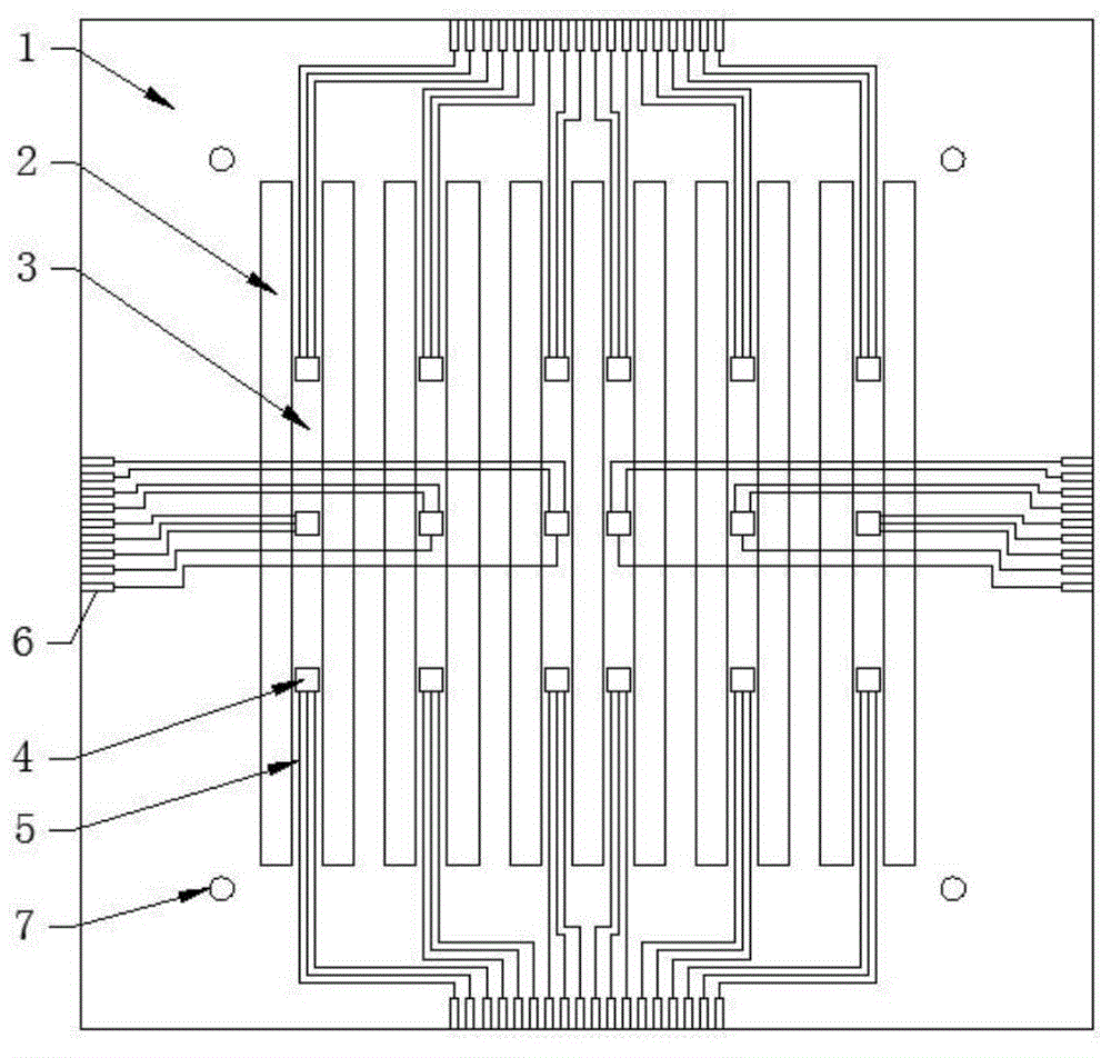
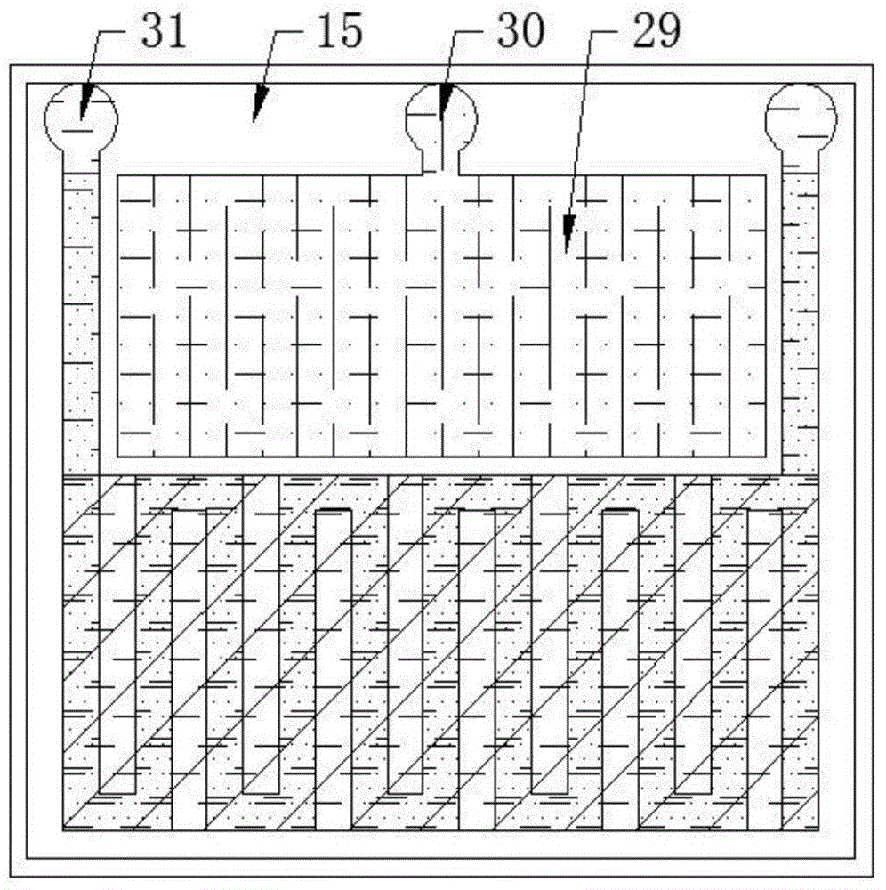
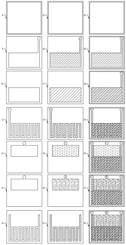
[0034] refer to figure 1As shown, the fuel cell internal humidity-current density distribution measurement insert of the present invention includes a conductive substrate 1, a leak 2, a rib 3, a humidity-current density joint measurement sensor 4, a lead wire 5, a pin 6, and a positioning hole 7 Leakage 2 and rib 3 are arranged on the conductive substrate 1, and it is identical with the flow channel and the ridge on the flow field plate of the fuel cell under test in shape and size, and the positions correspond to each other, and humidity-current is arranged on the rib 3 Density joint measurement sensor 4; one end of the lead wire 5 is connected to the humidity-current density joint measurement sensor 4, and the other end extends to the edge of the conductive substrate 1 for transmitting the electrical signal generated by the humidity-current density joint measurement ...


PUM

PropertyMeasurementUnit
Widthaaaaaaaaaa

Abstract

The invention discloses a fuel cell interior humidity-current density distribution measurement male tab, and the fuel cell interior humidity-current density distribution measurement male tab is a device for measuring fuel cell interior humidity distribution and electric current distribution, wherein a conductive substrate is provided with a leak and a tendon which correspond to a fuel cell flow field plate runner and a ridge, and a humidity-electric current density jointed measurement sensor is arranged on the tendon; the humidity-electric current density measurement sensor is manufactured by a vacuum evaporation coating method, and comprises seven layers of thin films. The vacuum evaporation coating method is adopted for manufacturing a leading wire used for transmitting an electric signal, and the leading wire extends to the edge of a flow field plate and then is enlarged to form a pin, so that the leading wire is conveniently connected with external data acquisition equipment. Synchronous on-line measurement of fuel cell interior humidity distribution and current density distribution is realized, the fuel cell interior humidity-current density distribution measurement male tab is independently arranged on a fuel cell, special remolding for the structure of the fuel cell is not needed, the fuel cell interior humidity-current density distribution measurement male tab is simple in structure, convenient in manufacturing and wide in application range, and is adaptive to a fuel cell flow field plate with a parallel runner, a snakelike runner, a stagger-type runner and other runner shapes.

Description

technical field [0001] The invention relates to an insertion piece for measuring humidity-current density distribution inside a fuel cell, and belongs to the technical field of fuel cell detection. Background technique [0002] As the electrochemical reaction inside the fuel cell proceeds, its internal humidity and local current density will also change. In the initial stage, the proton exchange membrane is not wetted, which affects the transfer of protons in the proton exchange membrane, so it is necessary to increase the humidity of the reaction gas to fully wet the proton exchange membrane; and as the running time increases, if the fuel Excessive humidity inside the battery will hinder the discharge of condensed water inside the fuel cell; the amount of condensed water will also affect the internal contact resistance of the fuel cell, resulting in changes in the local current density; through monitoring the current density, it can also reflect Changes in the gas concentr...

Claims


Application Information

Patent Timeline
IPC IPC(8): H01M8/04G01D21/02H01M8/04492
CPCH01M8/04492H01M8/04582Y02E60/50Y02P70/50
Inventor 郭航王政叶芳马重芳
Owner BEIJING UNIV OF TECH
Learn More