
Antenna structure and mobile terminal with antenna structure

An antenna structure and mobile terminal technology, applied to antennas, devices that make the antennas work in different frequency bands at the same time, telephone structures, etc. , Conducive to the effect of thinning

Active Publication Date: 2015-03-25
GUANGDONG OPPO MOBILE TELECOMM CORP LTD
View PDF5 Cites 3 Cited by
  • Summary
  • Abstract
  • Description
  • Claims
  • Application Information

AI Technical Summary

Problems solved by technology

) antenna and WIFI antenna, in order to avoid their mutual influence, they are generally set apart, but this takes up a lot of space and is not convenient for the layout of the antenna structure

Method used


Image

  • Antenna structure and mobile terminal with antenna structure
  • Antenna structure and mobile terminal with antenna structure

Examples


Embodiment 1

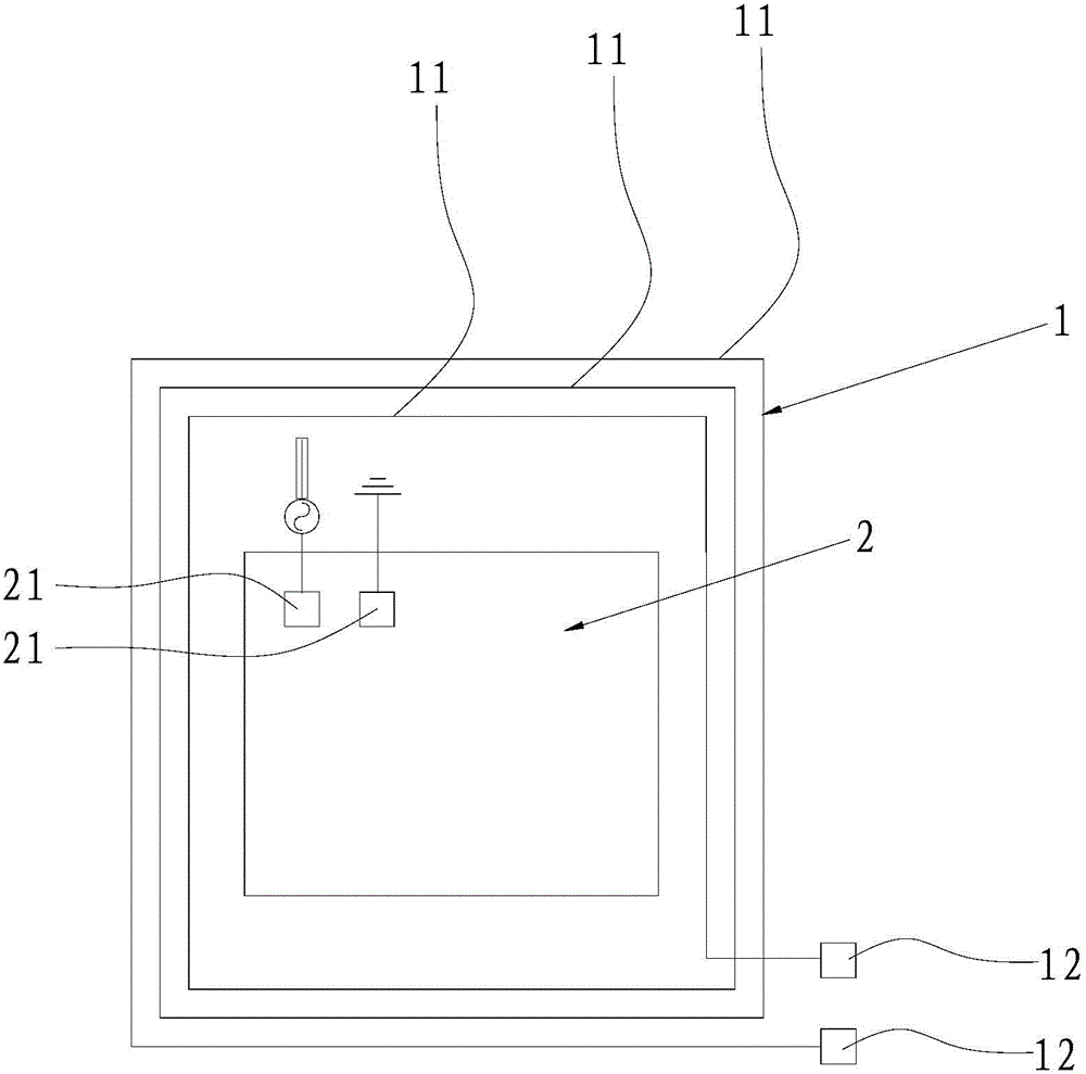
[0026] Such as figure 1 As shown, an antenna structure provided by the embodiment of the present invention includes a first antenna body 1, and the first antenna body 1 includes a spirally arranged antenna coil 11; The second antenna body 2 . The first antenna body 1 can work in the low frequency band, and the second antenna can work in the high frequency band, and the two will not affect each other. The first antenna body 1 can be located at the periphery of the second antenna body 2. In this embodiment, the first antenna body 1 can be a near field communication NFC antenna. technology. The second antenna body 2 may be a wireless fidelity WIFI (WIreless-Fidelity, wireless fidelity) antenna, and the operating frequency bands of the two are quite different, and the mutual influence between the first antenna body 1 and the second antenna body 2 will be relatively small. In this way, the NFC antenna and WIFI antenna can be arranged in a limited space, avoiding the high-frequen...

Embodiment 2

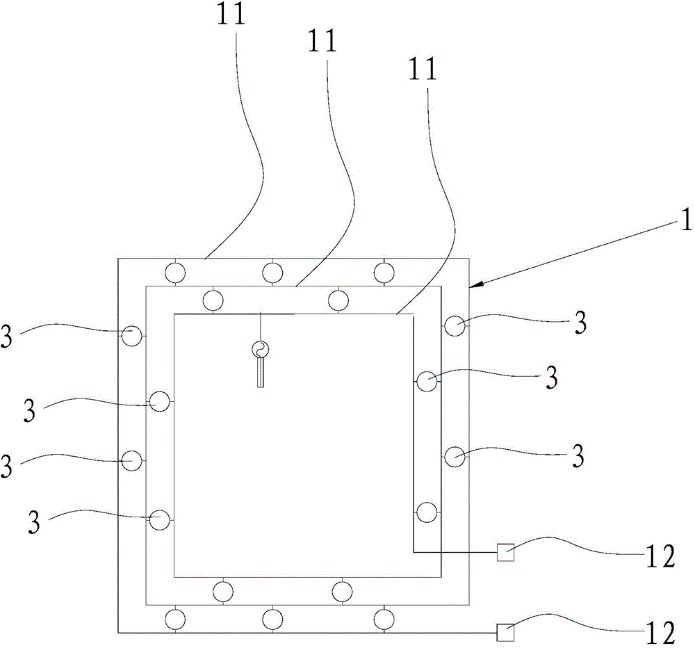
[0033] Such as figure 2 As shown, an antenna structure provided by an embodiment of the present invention includes a first antenna body 1, and the first antenna body 1 includes a spirally arranged antenna coil 11; a switch device that can be turned on or off is connected between the antenna coils 11 3. When the switching devices 3 are turned on, the antenna coils 11 are connected through the switching devices 3, so that the first antenna body 1 is equivalent to a piece of metal sheet. When working at low frequency, the switching device 3 is disconnected, and the first antenna body 1 is a coil. When the high frequency is used, the adjacent antenna coil 11 of the first antenna body 1 is turned on, causing the first antenna body 1 to become a whole piece of metal , which can be directly fed to form a high-frequency antenna. That is, when the switch device 3 is turned off, the first antenna body 1 can be used as an NFC antenna. That is, when the switch device 3 is turned on, t...


PUM


Abstract

The invention is suitable for the technical field of mobile terminals and discloses an antenna structure and a mobile terminal with the antenna structure. The antenna structure comprises a first antenna body which comprises a antenna coil which is arranged in a spiral mode. A second antenna body having the different working frequency with the first antenna body is arranged in the antenna coil, or / and switching devices which can be connected or disconnected are connected between the antenna coil. The mobile terminal is provided with the antenna structure. According to the antenna structure and the mobile terminal with the antenna structure, antennas can be arranged in the confined space, not too much space needs to be occupied additionally, arrangement is facilitated, lightness development of products is facilitated, and the performance of the antennas is reliable.

Description

technical field [0001] The invention belongs to the technical field of mobile terminals, and in particular relates to an antenna structure and a mobile terminal with the antenna structure. Background technique [0002] As the stacking of mobile terminals becomes more and more dense, there is less and less space left for designing antennas. Moreover, with the development of technology, the types of antennas for mobile terminals increase, such as NFC (Near Field Communication, near field communication, ie Short-range wireless communication technology.) Antenna and WIFI antenna, in order to avoid their mutual influence, they are generally set apart, but this takes up a lot of space and is not convenient for the layout of the antenna structure. Contents of the invention [0003] The object of the present invention is to overcome the disadvantages of the above-mentioned prior art, and provide an antenna structure and a mobile terminal with the antenna structure. The antenna occ...

Claims


Application Information

Patent Timeline
Patent Type & Authority Applications(China)
IPC IPC(8): H01Q5/30H04M1/02
Inventor 罗益州王新宝
Owner GUANGDONG OPPO MOBILE TELECOMM CORP LTD
Learn More