
Light dimension-reduction antenna used for near field test

A light-weight, near-field technology, applied to antennas, electrical components, etc., can solve the problems of excessive size and weight of pyramid horn antennas, and achieve the effect of improving performance and reducing geometric size

Active Publication Date: 2015-03-25
BEIJING INST OF ENVIRONMENTAL FEATURES
View PDF13 Cites 9 Cited by
  • Summary
  • Abstract
  • Description
  • Claims
  • Application Information

AI Technical Summary

Problems solved by technology

[0008] The purpose of the present invention is to propose a technical solution that can solve the problem that the size and weight of the pyramid horn antenna are too large

Method used


Image

  • Light dimension-reduction antenna used for near field test
  • Light dimension-reduction antenna used for near field test
  • Light dimension-reduction antenna used for near field test

Examples


Embodiment 1

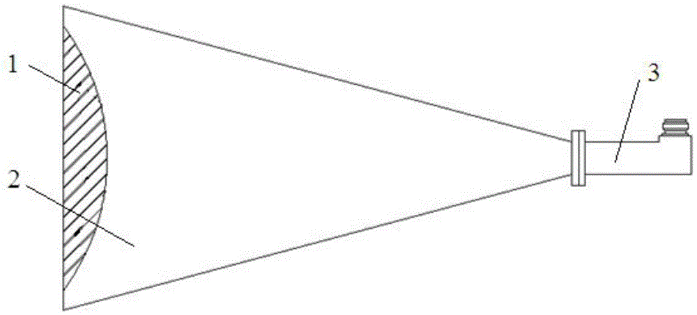
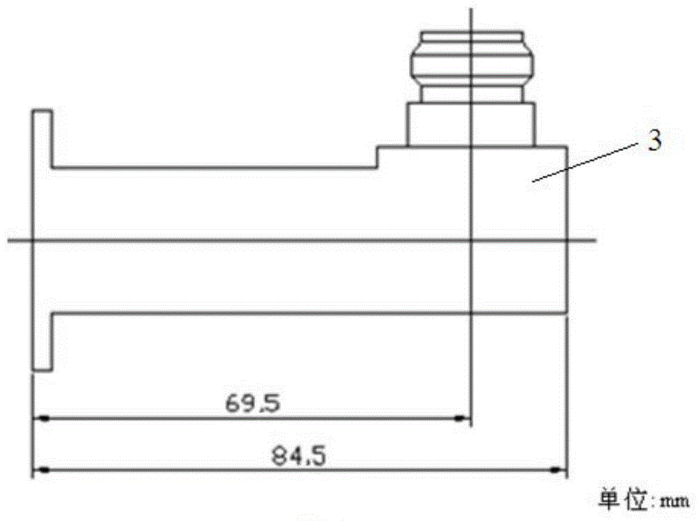
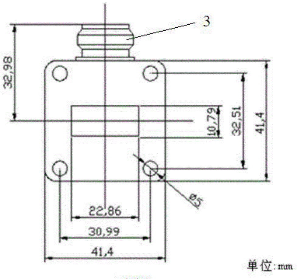
[0031] see figure 1 , according to the present invention, the lightweight and downsized antenna for near-field testing includes a horn antenna metal body 2, an elliptical arc-shaped dielectric loading lens 1 arranged at the bottom of the horn antenna metal body 2, and fixedly arranged on the horn antenna metal body 2 waveguide-to-coaxial converter 3 with cone top.

[0032] see Figure 4 , 5 And 6, the medium-loaded lens 1 is an elliptical arc, including a first bottom surface arranged at the bottom of the horn antenna metal body 2, two elliptical arc-shaped first planes vertically arranged on the front side and the rear side of the first bottom, respectively, and The first side is vertically arranged on the edge of the two elliptical arc-shaped first planes and is fixedly connected with the left side and the right side of the first bottom surface. The outer surface of the medium-loaded lens 1 is attached to the inner surface of the horn antenna metal body 2. Preferably, scr...

Embodiment 2

[0036] see figure 1 , according to the present invention, the lightweight and downsized antenna for near-field testing includes a horn antenna metal body 2, an elliptical arc-shaped dielectric loading lens 1 arranged at the bottom of the horn antenna metal body 2, and fixedly arranged on the horn antenna metal body 2 waveguide-to-coaxial converter 3 with cone top.

[0037] see Figure 7 , 8 And 9, the medium-loaded lens 1 is an elliptical arc, including a first bottom surface arranged at the bottom of the horn antenna metal body 2, two elliptical arc-shaped first planes vertically arranged on the front side and the rear side of the first bottom, respectively, and The first side is vertically arranged on the edge of the two elliptical arc-shaped first planes and is fixedly connected with the left side and the right side of the first bottom surface. The outer surface of the medium-loaded lens 1 is attached to the inner surface of the horn antenna metal body 2. Preferably, scr...


PUM


Abstract

The invention relates to a light dimension-reduction antenna used for a near field test. The light dimension-reduction antenna used for the near field test comprises a horn antenna metal body, a horn antenna metal body caliber portion, an oval arc-shaped medium loading lens and a waveguide coaxial transformer, wherein the oval arc-shaped medium loading lens is arranged at the horn antenna metal body caliber portion, and the vertex of a cone of the waveguide coaxial transformer is fixedly arranged at the vertex of a cone of the horn antenna metal body. According to the light dimension-reduction antenna used for the near field test, phase characteristics of radiation waves can be corrected at a short space distance through a convergence effect of the curve design of the oval arc-shaped medium loading lens, a transition section to be matched with a free space of the radiation waves can be shortened, therefore, the radiation waves can better approach uniform irradiation, the physical dimension of the antenna used for the near field test and the weight load of a testing system can be effectively reduced, and the performance of the near field test system can be improved.

Description

technical field [0001] The invention relates to the technical field of radar target characteristic testing, in particular to an antenna for near-field testing. Background technique [0002] The technical background related to the present invention will be described below, but these descriptions do not necessarily constitute the prior art of the present invention. [0003] The near-field test is to use the known probe to scan the surface of the antenna under test to obtain the amplitude and phase distribution on the surface of the antenna under test, and then use Fast Fourier Transformation (FFT) to enter the field The data is converted to far-field data. The antenna is an integral part of the test system, and its performance directly affects the test work. [0004] At present, the antenna of the near-field test system is generally a pyramid horn type, and the appearance has an important influence on the performance of the pyramid horn antenna. The near-field test system r...

Claims


Application Information

Patent Timeline
Patent Type & Authority Applications(China)
IPC IPC(8): H01Q19/08
Inventor 白杨高超
Owner BEIJING INST OF ENVIRONMENTAL FEATURES
Learn More