Method and device for controlling critical continuous mode unit power factor flyback converter

A critical continuous mode, unit power factor technology, applied in the output power conversion device, DC power input to DC power output, AC power input to DC power output and other directions, can solve the power factor and total harmonic distortion difference. , Unable to obtain unity power factor, large conduction loss, etc., to achieve the effect of small total harmonic distortion

Inactive Publication Date: 2015-03-25
SOUTHWEST JIAOTONG UNIV
View PDF6 Cites 9 Cited by
  • Summary
  • Abstract
  • Description
  • Claims
  • Application Information

AI Technical Summary

Problems solved by technology

The discontinuous mode flyback power factor correction converter can automatically obtain unity power factor, but due to its large peak current, the conduction loss of the switch tube is very large, which affects the efficiency of the converter
The traditional critical continuous mode flyback power factor correction converter, its control method is as follows figure 1 as shown, figure 2 It is the waveform o

Method used


Image

  • Method and device for controlling critical continuous mode unit power factor flyback converter
  • Method and device for controlling critical continuous mode unit power factor flyback converter
  • Method and device for controlling critical continuous mode unit power factor flyback converter

Examples


Embodiment Construction

[0021] The present invention will be further described in detail through specific examples and in conjunction with the accompanying drawings.

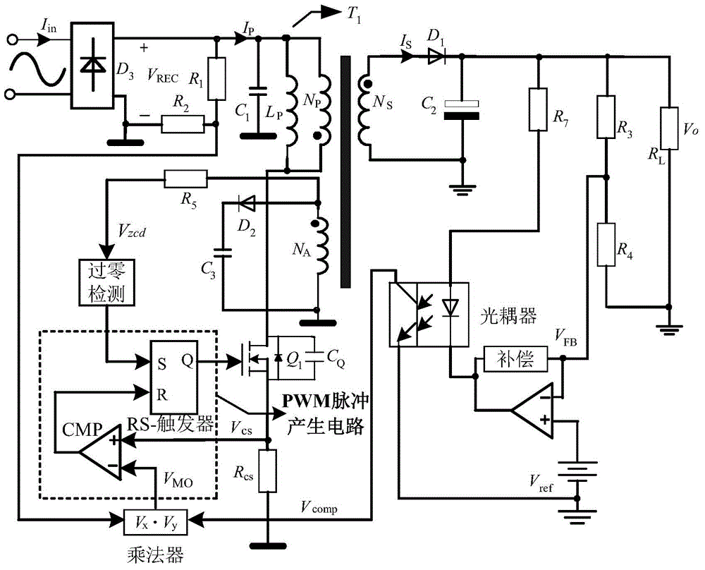
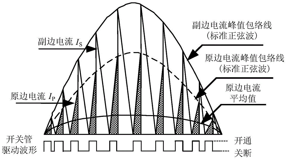
[0022] image 3 It is a system structure block diagram of the present invention, Figure 4 for image 3 The main waveform diagram of the shown circuit block diagram can be known from the waveform diagram that the flyback converter works in the critical continuous mode, and the peak current envelope of the primary switching tube of the present invention is no longer a standard sine wave, and compared with the traditional peak value In the current control method, the peak current envelope of the primary switching tube also adds information on the output voltage and the turns ratio of the primary and secondary sides of the transformer.

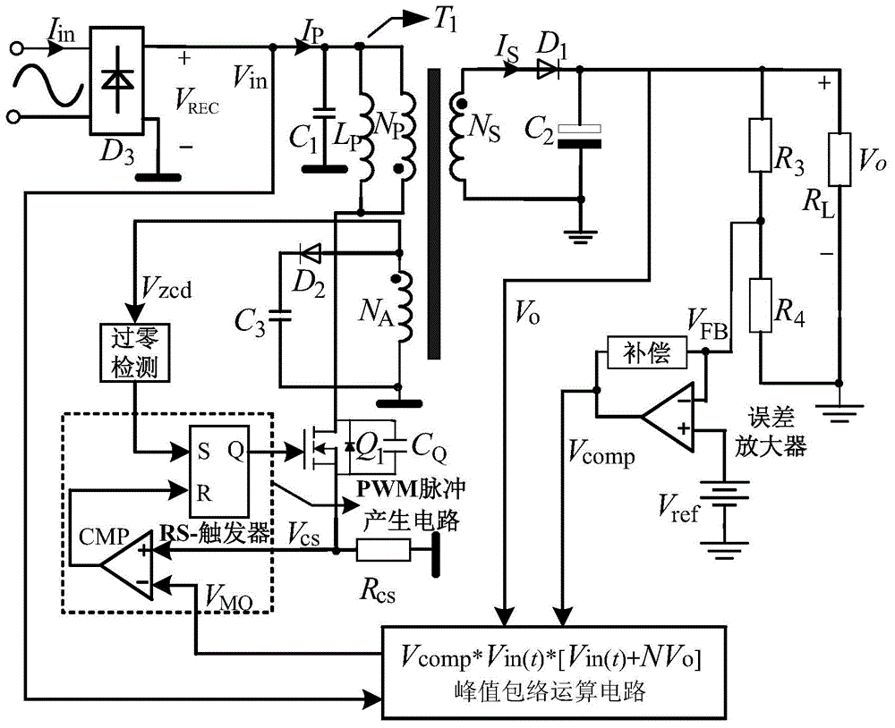
[0023] Figure 5 It is a specific embodiment of the present invention, a topology and control method of a critical continuous mode unity power factor flyback converter, and its specific method is:

[...


PUM


Abstract

The invention discloses a method and device for controlling a critical continuous mode unit power factor flyback converter. The method and device are used for improving the power factor of the critical continuous mode flyback converter. According to the method, the current peak envelope of a primary side switching tube of the critical continuous mode flyback converter is controlled, so that the current peak envelope of the switching tube changes along with changes of input voltage and output voltage within a power frequency cycle, and turn-off time of the switching tube is decided by the zero-crossing moment of a secondary side current of a transformer. Thus, the unit power factor of the critical continuous mode flyback converter can be obtained within the whole input voltage range.

Description

technical field [0001] The invention relates to power control equipment, in particular to a control method and device for a flyback power factor correction converter. Background technique [0002] In recent years, power electronics technology has developed rapidly, and power supply technology, which is an important part of the power electronics field, has gradually become a hot spot in application and research. Switching power supply has established its mainstream position in the field of power supply due to its high efficiency and high power density, but there is a fatal weakness when it is connected to the power grid through a rectifier: the power factor is low (generally only 0.45 to 0.75 ), and a large number of current harmonics and reactive power will be generated in the grid to pollute the grid. There are two main methods for suppressing harmonics generated by switching power supplies: one is the passive method, that is, using passive filtering or active filtering ci...

Claims


Application Information

Patent Timeline
IPC IPC(8): H02M3/335H02M1/42
CPCH02M1/42H02M3/33507H02M7/217Y02B70/10
Inventor 许建平何俊鹏高旭阎铁生高建龙
Owner SOUTHWEST JIAOTONG UNIV
Why Eureka
Try Eureka