Switch gear

A switchgear, switchgear technology, applied in the direction of switchgear, switchgear grounding device, electric switch, etc., to achieve the effect of saving space, reducing the number of parts, and reducing costs

A switchgear, switchgear technology, applied in the direction of switchgear, switchgear grounding device, electric switch, etc., to achieve the effect of saving space, reducing the number of parts, and reducing costs

CN104471806AActive Publication Date: 2015-03-25MITSUBISHI ELECTRIC CORP

Image

  • Switch gear
  • Switch gear
  • Switch gear

Examples


Embodiment approach 1

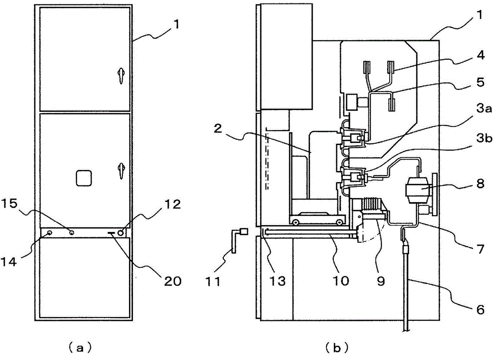
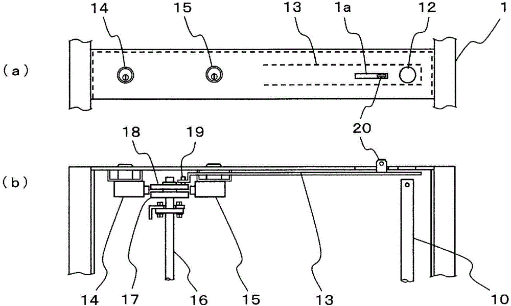
[0034] figure 1 The overall structure of the switchgear of Embodiment 1 is shown, in which, figure 1 (a) is the front view, figure 1 (b) is a side sectional view. also, figure 2 yes figure 1 An enlarged view of the interlock mechanism section of the , where, figure 2 (a) is the front view, figure 2 (b) is a bottom view of the interlock mechanism part.

[0035] First, use figure 1 , starting from the overall configuration of the switchgear according to the first embodiment.

[0036] The inside of the metal housing 1 is divided into a plurality of compartments. A drawer-type circuit breaker 2 is housed in the breaker compartment on the front side in such a manner that it can be pulled out from the front side. On the rear wall of the circuit breaker compartment, isolators for the main circuit are fixed at predetermined intervals in the vertical direction. The switch parts 3a, 3b are detachable from the connection terminals protruding from the back surface of the ...

Embodiment approach 2

[0079] Figure 10 It is an explanatory diagram showing the relationship between the opening and closing position of the shutter and the rotational position of the cam in the interlock mechanism portion of the switchgear according to the second embodiment. Figure 10 (a) means when the shutter is "open", Figure 10 (b) indicates when the shutter is "closed". also, Figure 11 It is an explanatory diagram showing the relationship between the opening and closing position of the switchgear in the interlock mechanism unit and the rotational position of the cam. Figure 10 (a) indicates that when the isolating switch described next is in "earth", Figure 10 (b) means that when the isolating switch is in "open circuit", Figure 10 (c) indicates when the isolating switch is "connected". The overall structure of the switchgear is the same as that of Embodiment 1 figure 1 The same, therefore, description is omitted.

[0080] In this embodiment, the switchgear to be interlocked is...


PUM


Abstract

A switch gear constructed such that a switching device and the operating shaft (10) therefor are housed in a case (1), with the switching device being switched on / off by inserting an operating handle (11) into a insertion port (12) from the outside and rotating the operating shaft (10), the switch gear being equipped with an interlock mechanism having: a shutter (13) that opens / closes the insertion port (12); a first cam (17) attached to a camshaft (16) that rotates in conjunction with the rotation of the operating shaft (10); a second cam (18) that rotates in conjunction with the switching of the shutter (13); a first lock (14), which can be locked by the engagement of a latch with recessed parts provided on both cams (17, 18), when the switching device is "off" and the shutter (13) is "closed"; and a second lock (15), which can be locked by the engagement of a latch with the recessed parts provided on both cams (17, 18), when the switching device is "on" and the shutter is "closed".

Description

technical field [0001] The invention relates to a switchgear, in which switchgear such as a disconnector switch or a grounding switch is accommodated in a frame of the switchgear, and includes a mechanism for locking the switchgear when the switchgear is in the "on" or "off" state. Key-type interlock mechanism. Background technique [0002] When performing maintenance and inspection on the high-voltage circuit of the switchgear, it is necessary to set the switches of the upper system and the lower system connected to the switchgear to the "OFF" state in advance, and to ground the circuit to be maintained and inspected. Since there may be residual charge in the circuit when it is not grounded, contact with the charging part and short-circuit accidents may occur. Therefore, it is necessary to adopt the following structure: by setting the structure that the key is pulled out after the grounding switch is locked in the "grounded" state, it can be mechanically locked in the grou...

Claims


Application Information

Patent Timeline
25 Mar 2015
Publication
CN104471806A
IPC
H02B11/133; H01H33/46; H02B1/30; H02B11/28
CPC
H01H9/22; H01H31/003; H02B11/133; H02B11/28
Inventors
小鹀进; 黑田崇士