
Safe and stable novel vibrating screen supporting beam

A technology of supporting beam and vibrating screen, which is applied in the direction of filter screen, solid separation, grid, etc., can solve the problems of large machining allowance, poor manufacturing level, large material used for supporting beam flange, etc., and achieve a reasonable and balanced force distribution and reduce The effect of small noise volume and guaranteed position accuracy

Inactive Publication Date: 2015-04-01
AURY TIANJIN IND TECH
View PDF0 Cites 3 Cited by
  • Summary
  • Abstract
  • Description
  • Claims
  • Application Information

AI Technical Summary

Problems solved by technology

Due to the short development time, low technical content, and poor manufacturing level of the support beams manufactured by some domestic manufacturers, they have not been improved in time, it is difficult to finalize and promote, and the products cannot meet higher requirements for use. Therefore, most coal preparation plants choose better quality Imported products, but after all, the price is high and the delivery cycle is long. At the same time, it is difficult to connect the support beam in the prior art. When the flange and the steel pipe are connected, the flatness and verticality cannot be guaranteed. Too large, large processing allowance, waste of materials, waste of man-hours, low efficiency, and the two ends of the currently used vibrating screen are not sealed, and they are open. Under the action of material impact and high-frequency vibration, the measuring point is outward. pass a lot of noise

Method used


Image

  • Safe and stable novel vibrating screen supporting beam
  • Safe and stable novel vibrating screen supporting beam

Examples


Embodiment 1

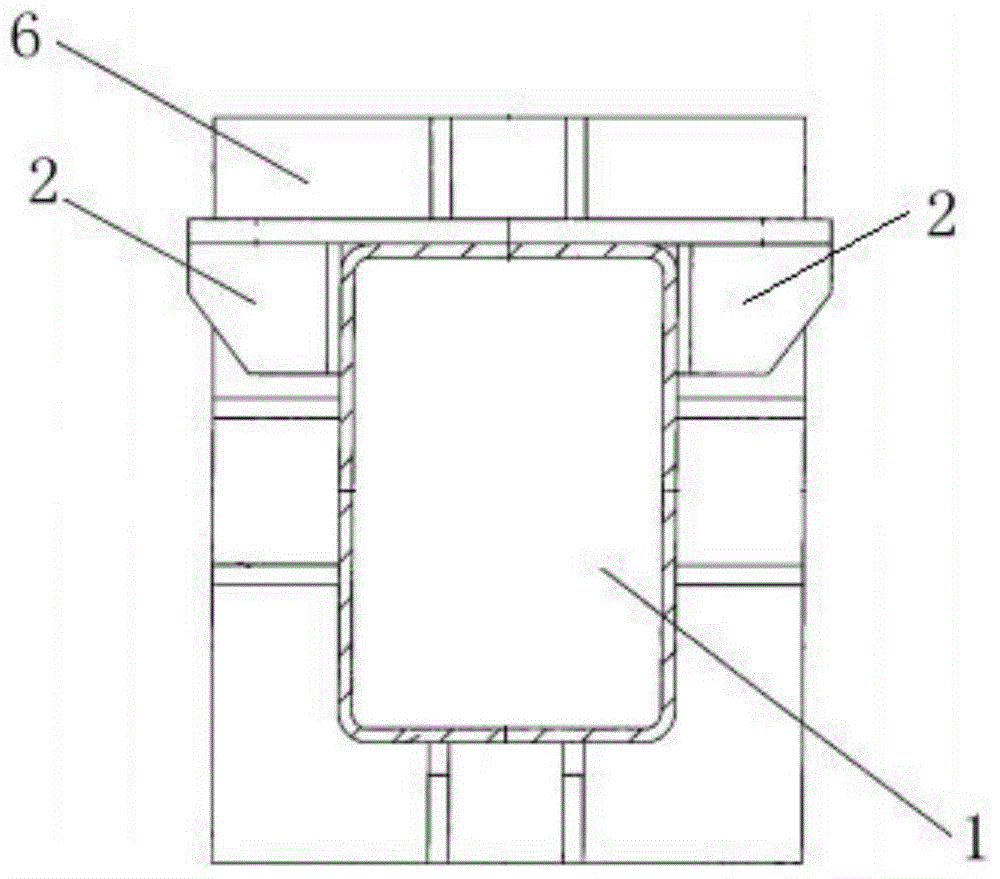
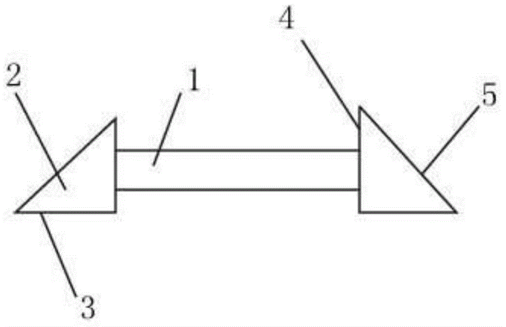
[0018] A new type of safe and stable vibrating screen support beam, including a support beam 1, a docking seat 2, and a flange 6, the left and right sides of the support beam 1 are provided with a docking seat 2, one end of the support beam 1 is provided with a flange 6, and the docking seat 2 Including the bottom plate 3, the vertical plate 4 and the inclined support plate 5, the bottom plate 3, the vertical plate 4, and the inclined support plate 5 are connected in sequence, the vertical plate 4 is provided with bolt holes, and the vertical plate 4 is fixed to the flange 6 through the bolt holes Together, the support beam 1 is provided with a support bracket and a washer, the support bracket is provided with the washer, and the surface of the support beam 1 is provided with an erosion-resistant corrosion layer.

Embodiment 2

[0020] A safe and stable new vibrating screen support beam, comprising a circular tube hollow support beam, a docking seat 2, and a flange 6. The left and right sides of the circular tube hollow support beam are provided with a docking seat 2, and one end of the support beam 1 is provided with a flange. Lan 6, the docking seat 2 includes a base plate 3, a vertical plate 4 and an inclined support plate 5, the base plate 3, the vertical plate 4, and the inclined support plate 5 are connected in sequence, the vertical plate 4 is provided with bolt holes, and the vertical plate 4 passes through the bolts The hole and the flange 6 are fixed together, the support beam 1 is provided with a support bracket and a gasket, the support bracket is provided with the gasket, and the surface of the support beam 1 is provided with an erosion-resistant corrosion layer.

Embodiment 3

[0022] A safe and stable new vibrating screen support beam, comprising a circular tube hollow support beam, a docking seat 2, and a flange 6. The left and right sides of the circular tube hollow support beam are provided with a docking seat 2, and one end of the support beam 1 is provided with a flange. Lan 6, the docking seat 2 includes a base plate 3, a vertical plate 4 and an inclined support plate 5, the base plate 3, the vertical plate 4, and the inclined support plate 5 are connected in sequence, the vertical plate 4 is provided with bolt holes, and the vertical plate 4 passes through the bolts The hole is fixed with the flange 6, and the flange 6 is provided with an air vent, and the bracket bracket and the gasket are fixed on the hollow support beam of the round tube through a rivet, and the bracket bracket is provided with the The washer, the surface of the hollow support beam of the round tube is provided with an erosion-resistant corrosion layer.


PUM


Abstract

The invention provides a safe and stable novel vibrating screen supporting beam. The safe and stable novel vibrating screen supporting beam comprises a supporting beam, butting bases and a flange, wherein the butting bases are respectively arranged on the left and right sides of the supporting beam; the flange is arranged at one end of the supporting beam; each butting base comprises a base plate, a vertical plat and an oblique supporting plate which are connected with one another sequentially; each vertical plate is provided with a bolt hole and is fixed together with the flange by the bolt hole; the supporting beam is provided with a bracket rack and a gasket; the gasket is arranged on the bracket rack; a scouring-corrosion-resisting layer is arranged on the surface of the supporting beam. The safe and stable novel vibrating screen supporting beam provided by the invention has the beneficial effect that the safe and stable novel vibrating screen supporting beam has the characteristics of being resistant to scouring and corrosion, large in structural rigidity, high in strength, reasonable and balanced in stress distribution, high in safety coefficient, compact in structure, light in weight and the like.

Description

technical field [0001] The invention relates to the technical field, and more specifically relates to a safe and stable novel vibrating screen support beam. Background technique [0002] The vibrating screen works by using the high-efficiency reciprocating linear vibration force generated by the exciter to act on the screen body. The vibrating screen support beam plays a great role on the vibrating screen. With the continuous improvement of the technical requirements for vibrating screen screening, there is an urgent need for a support beam with high rigidity, high strength, high safety factor and long service life to be used in vibrating screens. . Due to the short development time, low technical content, and poor manufacturing level of the support beams manufactured by some domestic manufacturers, they have not been improved in time, it is difficult to finalize and promote, and the products cannot meet higher requirements for use. Therefore, most coal preparation plants c...

Claims


Application Information

Patent Timeline
Patent Type & Authority Applications(China)
IPC IPC(8): B07B1/46B07B1/28
CPCB07B1/46B07B1/28
Inventor 张晋喜刘波
Owner AURY TIANJIN IND TECH
Learn More