Reverse boring cutter

A technology of back-boring cutters and tool holders, which is applied in the direction of boring heads, accessories of tool holders, and tools used in lathes, etc., which can solve the problems of high manufacturing cost, low durability, and complex structure of back-boring cutters, and reduce energy consumption. Consumption, saving resources, and reducing operating costs

Active Publication Date: 2015-04-01
太原北方永磁电机科技有限公司
View PDF7 Cites 2 Cited by
  • Summary
  • Abstract
  • Description
  • Claims
  • Application Information

AI Technical Summary

Problems solved by technology

[0003] The purpose of the present invention is to solve the problems of complex structure, high manufacturing cost and low durability of the existing back-boring cutter, and propose a back-boring cutter, which is suitable for CNC machine tools with the internal cooling function of the main shaft

Method used


Image

  • Reverse boring cutter
  • Reverse boring cutter
  • Reverse boring cutter

Examples


Embodiment Construction

[0033] The present invention will be described in detail below with reference to the accompanying drawings and embodiments, and the technical problems and beneficial effects solved by the technical solutions of the present invention will also be described. It should be pointed out that the described embodiments are only intended to facilitate the understanding of the present invention, and It does not have any limiting effect on it.

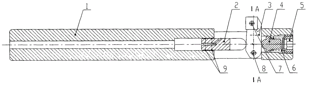
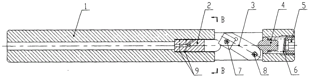
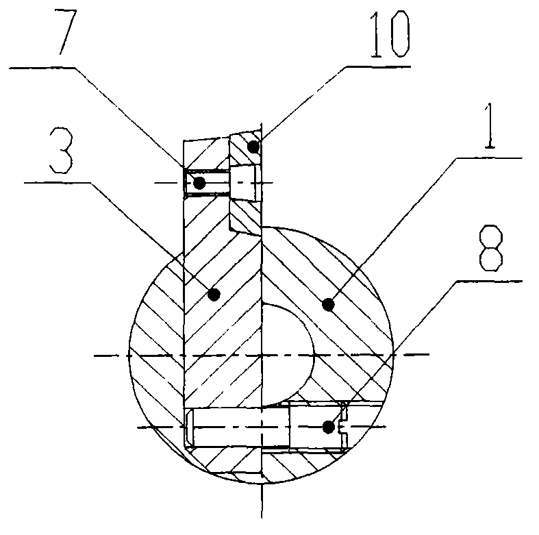
[0034] like figure 1 , figure 2 , image 3 , Figure 4 , Figure 5 and Image 6 As shown, it is an example of an anti-boring tool based on the content of the present invention, including a tool holder 1, a slide valve 2, a tool holder 3, a ejector rod 4, a plug cover 5, a spring 6, a compression screw 7, a pin 8, O-ring 9, blade 10, positioning screw 11, a high-pressure coolant through hole 101 is provided at the tail of the cutter bar 1; The body is provided with a hole 106 for installing the positioning screw 11 ; the head is provided wi...


PUM


Abstract

The invention relates to a reverse boring cutter, and belongs to the technical field of a machining cutter. The reverse boring cutter comprises a cutter bar (1), a cutter body, a slide valve (2), a mandril (4), a blanking cap (5), a spring (6) and a hinge pin (8), wherein the tail part of the cutter bar is provided with a high through cooling fluid through hole (101), the middle part of the cutter bar is provided with a cavity (102) for holding the slide valve and a cavity (103) for holding the cutter body, and the head of the cutter bar is provided with a cavity (104) for holding the mandril, a spring and the blanking cap and a hole for installing the hinge pin (8); the slide valve is arranged in the cavity (102), and can slide axially along the cutter bar, the cutter body is installed in the cavity (103) through the hinge pin and can rotate freely by taking the hinge pin as a shaft in the cavity, the mandril sliding axially along the cutter bar and the spring fixedly connected with the cutter bar are arranged in the cavity (104). According to the reverse boring cutter provided by the invention, the problems that the reverse boring cutter is complicate in structure, high in manufacturing cost and low in durability, and cooling equipment needs to be installed additionally at work can be solved.

Description

technical field [0001] The invention relates to an anti-boring tool, which belongs to the technical field of machining tools. Background technique [0002] The machining of traditional reverse countersinking usually adopts the method that the tool bar passes through the machined through hole and manually loads the boring tool from the opposite direction. Factors such as cavity size make it impossible to manually load the tool. With the development of tool design technology, various forms of counterboring tools have appeared one after another, with the functions of forward feeding and automatic opening and closing of the tool holder, which continuously improves the processing ability of reverse countersinking and realizes high-efficiency machining. . For example, Invention 201010127220.2 discloses a reverse boring tool that utilizes the reverse and forward rotation of the tool holder to realize the recovery and opening of the tool body. However, on the one hand, the design...

Claims


Application Information

Patent Timeline
Patent Type & Authority Applications(China)
IPC IPC(8): B23B27/00B23B27/10B23B29/03
CPCB23B27/10B23B29/08
Inventor 冯雪山薛维毅武文虎李有生王飞
Owner 太原北方永磁电机科技有限公司
Why Eureka
Try Eureka