Eureka AIR delivers breakthrough ideas for toughest innovation challenges, trusted by R&D personnel around the world.

Cast-in-place concrete pile air bubble elimination casting device

A technology of air bubble elimination and cast-in-place pile, which is applied in construction and foundation structure engineering, etc., and can solve problems such as difficulty in vibrating, concrete pouring pile vibrating, mixing difficulty, and inability to reach the vibrator

Inactive Publication Date: 2015-04-01
六盘水为强混凝土有限责任公司
View PDF4 Cites 6 Cited by
  • Summary
  • Abstract
  • Description
  • Claims
  • Application Information

AI Technical Summary

Problems solved by technology

However, the concrete pouring piles that adopt the drilling process also have their defects: the quality of the concrete pouring has a great influence on the bearing capacity of the piles. If air bubbles appear in the pouring process, honeycombs will be formed on the pile body, and these honeycombs will seriously reduce the bearing capacity of the piles. carrying capacity
However, in the existing technology, the concrete with a relatively large slump is only used to form a pile by its own weight, and the pile body is not compacted by techniques such as vibration and mixing. This is because the vibration and mixing of concrete pouring piles have objective difficulties. First of all, the pile length of cast-in-situ piles is generally more than ten meters to tens of meters, and the vibrating rod cannot reach such a deep depth at all. If the condition is inside, it is difficult to vibrate and the effect is not good

Method used


Image

  • Cast-in-place concrete pile air bubble elimination casting device
  • Cast-in-place concrete pile air bubble elimination casting device
  • Cast-in-place concrete pile air bubble elimination casting device

Examples


Embodiment Construction

[0027] Embodiments of the present invention will be further described in detail below in conjunction with the accompanying drawings.

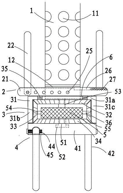
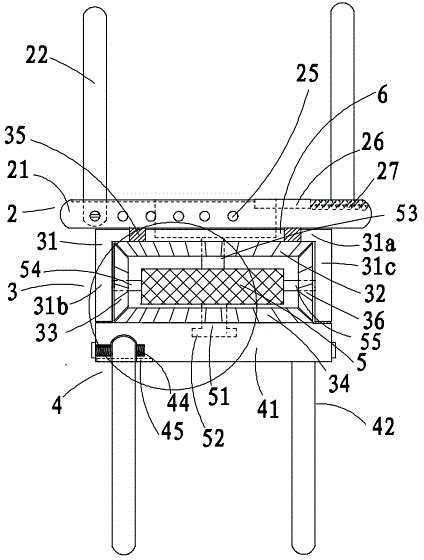
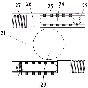
[0028] Figure 1 to Figure 14 Shown is the structural representation of the present invention.

[0029] The reference signs are: pouring pipe 1, discharge hole 11, fixed port 12, upper stirring device 2, upper rotating plate 21, upper stirring column 22, upper plate center hole 23, upper adjusting groove 24, upper adjusting fixing hole 25. Push-up plate 26, push-up spring 27, middle transmission structure 3, transmission support 31, top support plate 31a, left support plate 31b, right support plate 31c, top helical gear 32, left helical gear 33, bottom Helical gear 34, connecting column 35, right side helical gear 36, bottom stirring device 4, lower rotating plate 41, lower stirring column 42, lower adjustment groove 43, lower adjustment fixing hole 44, lower push plate 45, lower push spring 46, Motor 5, power transmission shaft 51, shaft hea...


PUM


Abstract

The invention discloses a cast-in-place concrete pile air bubble elimination casting device. A discharging hole is formed in the side wall of the lower part of a casting pipe, the bottom of the casting pipe is connected with an air bubble eliminator, the air bubble eliminator comprises an upper layer stirring device, a middle layer transmission structure and a bottom layer stirring device in sequential arrangement from top to bottom, the upper layer stirring device and the bottom layer stirring device can rotate in the same direction or in the opposite direction through being driven by the middle layer transmission structure, and the extending-out length of a stirring post can be respectively regulated by the upper layer stirring device and the bottom layer stirring device, so that the cast-in-place concrete pile air bubble elimination casting device can be applicable to casting piles with different pile diameters, the air bubble eliminator can ascend or descend along with the casting pipe, and the use is convenient. The cast-in-place concrete pile air bubble elimination casting device has the advantages that the air bubble eliminator can be prevented from being clamped in a steel bar cage during descending through a position limiting sleeve, and the service life of the air bubble elimination casting device is effectively prolonged.

Description

technical field [0001] The invention relates to the technical field of civil engineering, in particular to a pouring device for eliminating air bubbles of concrete pouring piles. Background technique [0002] The cast-in-situ concrete pile is a kind of pile formed by directly forming a hole on the spot pile position, and then pouring concrete in the hole or placing a steel cage and then pouring concrete. The characteristic is that the pile diameter can be selected according to the needs, and piles with a diameter much larger than that of prefabricated piles can be built. Compared with the hammering method in sinking piles, the construction noise and vibration are much smaller, and it can be applied to various foundations. There are generally two types of existing concrete cast-in-place piles: immersed tube cast-in-place piles and bored cast-in-place piles. Among them, immersed tube cast-in-place piles use hammering pile sinking equipment to sink tubes and pull out tubes to f...

Claims


Application Information

Patent Timeline
Patent Type & Authority Applications(China)
IPC IPC(8): E02D15/04
CPCE02D15/04E02D2250/0023
Inventor 杜新勇曾新平郑春娥
Owner 六盘水为强混凝土有限责任公司
Why Eureka
Eureka Blog
Learn More