Internal mixer rotor sealing device

A technology of rotor sealing and internal mixer, applied in the direction of engine sealing, mechanical equipment, engine components, etc., can solve the problems of wear and leakage, small maintenance, low maintenance cost, etc., to improve quality, small maintenance, maintenance low cost effect

Inactive Publication Date: 2015-04-01
QINGDAO UNIV OF SCI & TECH
View PDF12 Cites 3 Cited by
  • Summary
  • Abstract
  • Description
  • Claims
  • Application Information

AI Technical Summary

Problems solved by technology

[0006] Compared with the prior art, the present invention solves the problem of material leakage after long-term use in the traditional sealing method, integrates the magnetic medium seal into the seal of the internal mixer, utilizes the cooperation of the permanent magnetic pole and the pole shoe to form a magnetic field force, and The labyrinth seal is integrated into the magnetic medium seal, and the sleeve is set as a helical threaded sleeve to form a back pressure during rotation, so that most of the compounding agent leaked from the gap is absorbed by the dual action of magnetic field force and back pressure. Send it back to the mixing room, the residual part is fused in the magnetic medium, and the real-time adjustment of the sealing pressure can be realized by adjusting the rotor speed; indirectly, the compounding agent and the matrix glue are more fully mixed, ensuring the production or experiment. The amount of agent used improves the quality of rubber products; in terms of maintenance, magnetic medium seals require less maintenance than contact seals such as mechanical seals, packing seals, oil seals, etc., and will not cause any wear and damage to the rotor shaft; the structure of the device Simple, scientific principle, novel design, strong operability, good sealing effect, long service life, low maintenance cost, friendly working environment

Method used


Image

  • Internal mixer rotor sealing device
  • Internal mixer rotor sealing device
  • Internal mixer rotor sealing device

Examples


Embodiment

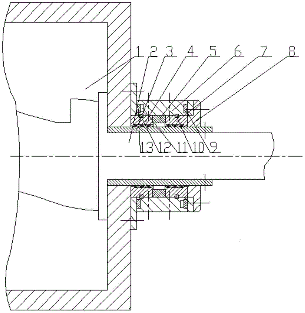
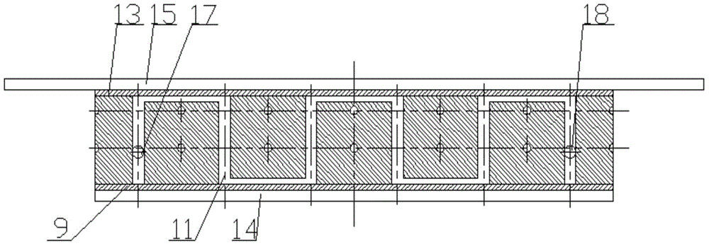
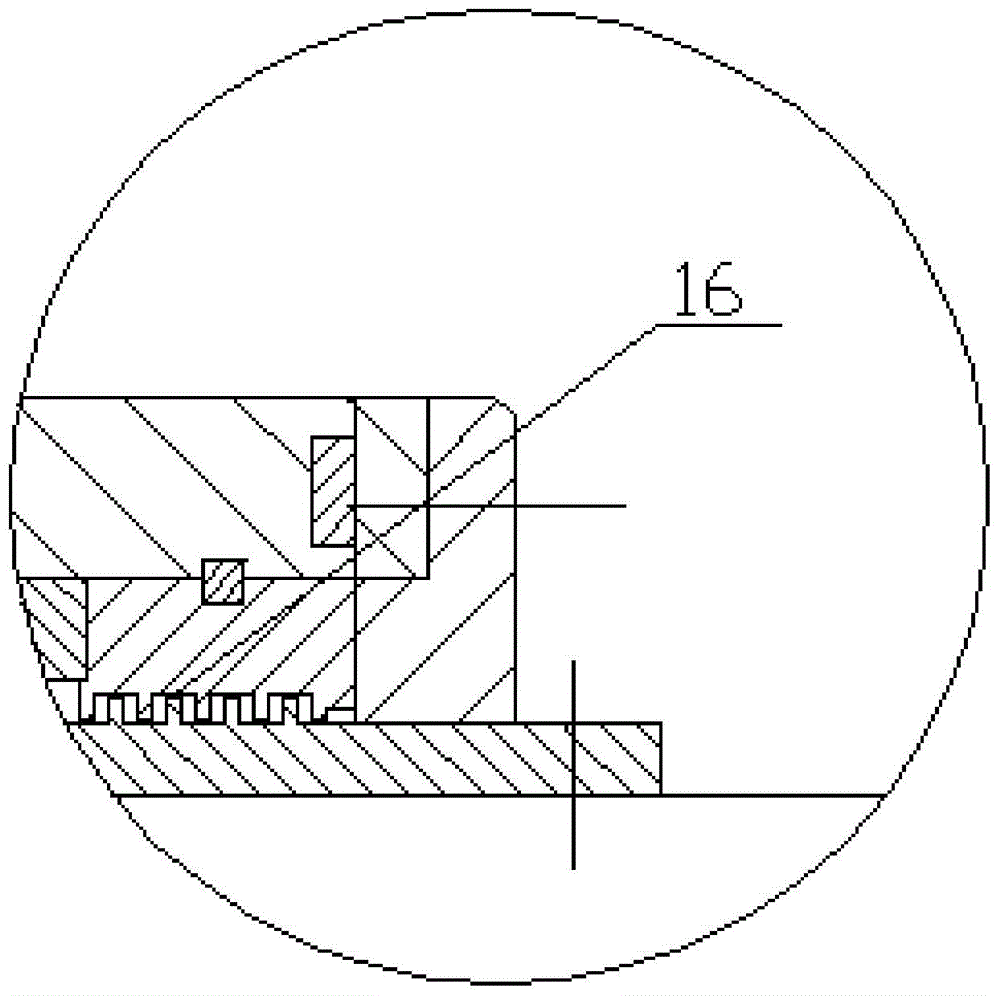
[0012] The rotor sealing device of the internal mixer involved in this embodiment is integrally arranged on the exposed rotor shaft 2 of the internal mixing chamber 1, and its main structure includes a threaded shaft sleeve 3, a No. Ⅰ pole shoe 4, a permanent magnet 5, a housing 6, and a No. Ⅱ pole Boot 7, end cover 8, Ⅰ sealing cover 9, Ⅰ O-ring 10, cooling channel 11, Ⅱ O-ring 12, Ⅱ sealing cover 13, end flange 14, fixed flange 15 , Magnetic medium 16, liquid inlet 17 and liquid outlet 18, of which No. Ⅰ pole piece 4, No. Ⅱ pole piece 7 and shell 6 are all symmetrically split structures. The threaded shaft sleeve 3 is tightly sleeved on the rotor by screw fixing On the shaft 2, one end of the shell 6 sheathed on the threaded sleeve 3 is fixedly connected to the outer wall of the mixing chamber 1 by screws, and the other end of the shell 6 is fixedly connected with an end cover 8 by screws, and the inner cavity wall of the shell 6 No. Ⅰ pole piece 4 and No. Ⅱ pole piece 7 are ...


PUM


Abstract

The invention belongs to the technical field of the sealing of a rubber device, and relates to a novel internal mixer rotor sealing device. A threaded shaft sleeve fixedly sleeves a rotor shaft, one end of a shell is fixedly connected to the outer wall of an internal mixing chamber, the other end of the shell is fixedly butt-jointed to an end cover, a first pole shoe and a second pole shoe are fixed on the wall of an inner cavity of the shell, and a permanent magnet is installed in a space between the two pole shoes in an embedding manner; a second O-shaped sealing ring and a first O-shaped sealing ring are respectively arranged on the junctions between the inner cavity wall of the shell and the two pole shoes, a clearance between each pole shoe and the outer wall of the threaded shaft sleeve is filled with a magnetic medium; a cooling passage with a liquid inlet and a liquid outlet in two ends is formed in the inner cavity of the shell, a second sealing cover plate and a first sealing end cover are respectively welded on the cooling passage on the end, which is butt-jointed with the outer wall of the internal mixing chamber, of the shell and the end, which is butt-jointed with the end cover, of the shell, and an end flange and a fixed flange are welded on the periphery of the shell. The novel internal mixer rotor sealing device is simple in structure, novel in design, high in operability, good in sealing effect and long in service life.

Description

Technical field: [0001] The invention belongs to the technical field of rubber equipment sealing, and relates to a new type of internal mixer rotor sealing device. The magnetic medium sealing technology is applied to the internal mixer rotor sealing, which effectively improves the sealing effect. Background technique: [0002] Nowadays, the production of rubber compound is mainly carried out by an internal mixer. In the internal mixer, the base rubber, compounding agents and granular additives are uniformly dispersed and mixed, which is an efficient mixing method, and the internal mixer is working. At this time, the gap between the rotor shaft diameter and the side wall of the mixing chamber is likely to cause the above-mentioned compounding agent to leak, so as to affect the mixing effect of the matrix glue and compounding agent; in order to prevent the leakage phenomenon, people initially passed the fine and easily dispersed components through Oil film adhesion is processed, bu...

Claims


Application Information

Patent Timeline
Patent Type & Authority Applications(China)
IPC IPC(8): F16J15/16F16J15/53
CPCF16J15/16
Inventor 汪传生潘弋人徐小林吴浩王蒙边慧光李绍明
Owner QINGDAO UNIV OF SCI & TECH
Why Eureka
Try Eureka