Automatic vacuum spraying process method

A technology of vacuum spraying and process method, which is applied in the fields of food, aquatic feed processing, and pet food. It can solve problems such as tight closure, air leakage risk, and uneven spraying, and achieve good sealing performance, easy cleaning, and fast discharge. Effect

Inactive Publication Date: 2020-03-27
远腾自动化设备(扬州)有限公司
View PDF9 Cites 6 Cited by
  • Summary
  • Abstract
  • Description
  • Claims
  • Application Information

AI Technical Summary

Problems solved by technology

[0003] The helical blades of the auger of the device spirally extend to the bottom of the tank body along the conical surface of the cone body. When working, the helical blades of the auger scrape up the granular materials at the bottom of the tank body and transport them to the upper side of the tank body to be mixed with the atomized liquid droplets. Contact, but its disadvantages are: the inner wall of the spiral casing and the internal spiral blades are cleaning dead angles, which cannot be cleaned by compressed air or manually, and the added oil is atomized and sprayed, and will be bonded to the spiral with the powder in the material; After spraying the material many times, the inside of the tank is not cleaned cleanly, and bacteria are easy to breed, which makes it impossible to meet the requirements of food hygiene; the conical discharge door is easy to stick to the material, resulting in poor closure and the risk of air leakage; the single auger cannot fully stir the material , the spraying is not uniform enough, the internal volume of the tank is not large enough, and the efficiency of spraying and processing materials is low

Method used


Image

  • Automatic vacuum spraying process method
  • Automatic vacuum spraying process method
  • Automatic vacuum spraying process method

Examples


Embodiment 1

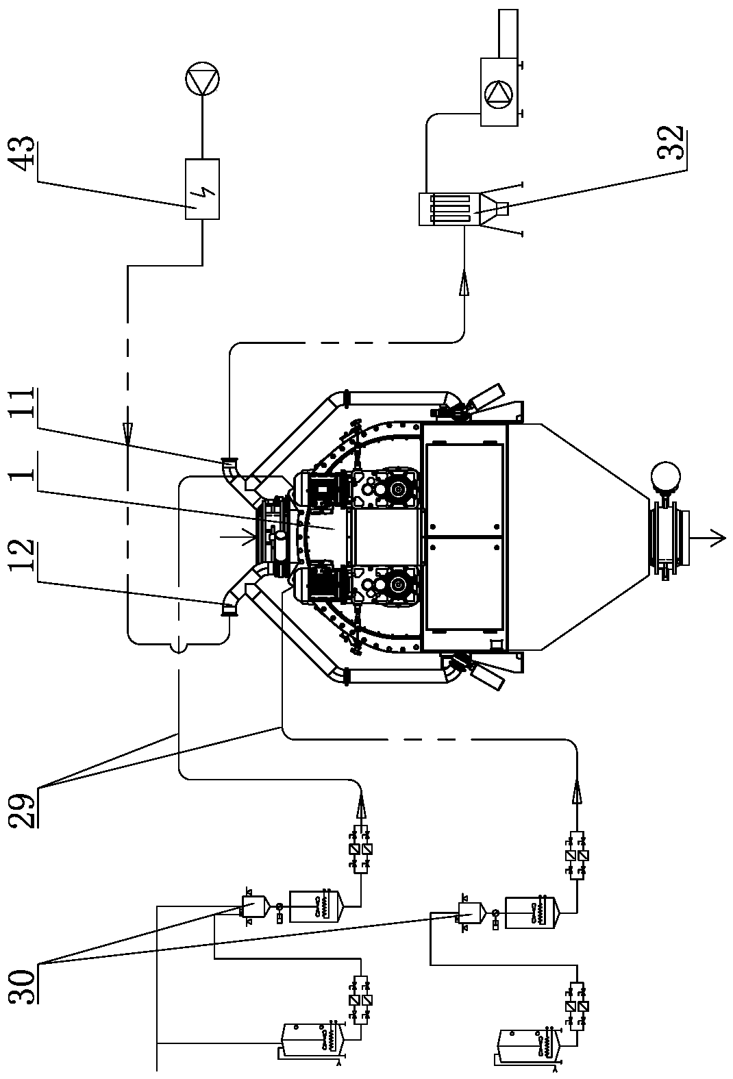
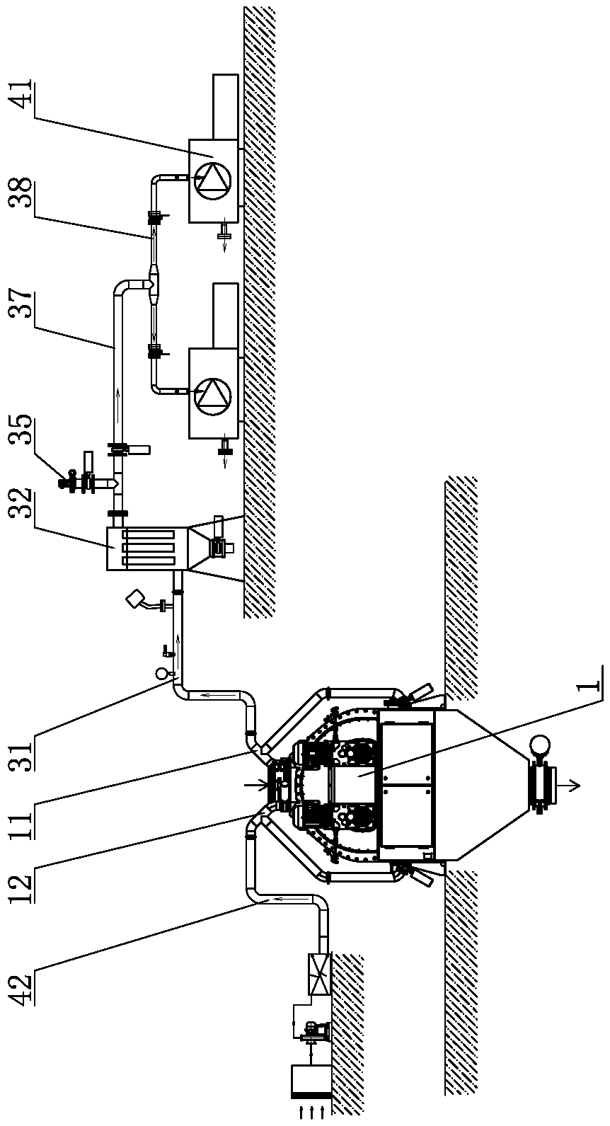
[0043] The automatic vacuum spraying process method of the present embodiment, as Figure 1-12 As shown, it includes the spraying host 1, the top of the spraying host 1 is provided with a material inlet 2, the inside of the spraying host 1 is provided with a mixing chamber 101, and the bottom of the spraying host 1 is provided with a discharge port 9, and there are 2 feed ports and 9 discharge ports Both are provided with disc valves 36, and the mixing chamber 101 includes two left and right symmetrical sub-chambers 101a, and a stirring shaft 3 is rotatably arranged in the two sub-chambers 101a respectively, and the stirring shaft 3 is connected with the spraying host 1 sub-chamber 101a The length direction of the mixing shaft 3 is set parallel to each other. A number of paddles 5 are staggered on the stirring shaft 3. The paddles 5 on the two stirring shafts 3 are staggered along the circumferential direction. The two stirring shafts 3 are connected to the rotating drive mecha...

Embodiment 2

[0063] The difference from Example 1 is that, as Figure 13 and 14 , the first nozzle assembly 13 is connected to the pumping pipeline 1301 located above, the first nozzle assembly 13 includes a left branch pipe 1301a, a right branch pipe 1301b and a right branch pipe 2 1301c, and the left branch pipe 1301a is provided with Six nozzles 26, four nozzles 26 are arranged on the right branch pipe one 1301b and the right branch pipe two 1301c; the second nozzle assembly 13 is connected with the pumping pipeline 1302 located below, and the second nozzle assembly 13 includes a left branch Pipe 2 1302a and right branch pipe 3 1302b, left branch pipe 2 1302a is provided with four nozzles 26, right branch pipe 3 1302b is provided with two nozzles 26, left branch pipe 2 1302a is set corresponding to left branch pipe 1 1301a , the right branch pipe three 1302b is set corresponding to the right branch pipe one 1301b and the right branch pipe two 1301c; the outlet of the nozzle 26 is provi...

Embodiment 3

[0075] The difference from Example 1 is that the processing method of this embodiment includes the following steps:

[0076] (1) Self-inspection: The weighing sensor of the material adding equipment performs a self-inspection reset, and the reset time is 6s;

[0077] (2) Feeding: The material adding equipment weighs 500kg of material granules, the material is extruded aquatic product material, the size of the material granules is 6~18mm, and the bulk density of the material granules is 0.3~0.7t / m 3 , feed the material particles into the mixing chamber 101 through the feed port 2, when the disc valve 36 of the feed port 2 is opened, the drive motor 7 of the stirring shaft 3 starts to run at a motor frequency of 32Hz, and the feeding process lasts for 19s;

[0078] (3) Vacuuming: Close the butterfly valve 36 of the feed port 2, open the butterfly valve connected to the vacuum tube 11, start the vacuum pump 41, and vacuum the inside of the mixing chamber 101 to 0.1 bar, and the d...


PUM


Abstract

The invention discloses an automatic vacuum spraying process method in the field of food, pet food and aquatic feed processing. The automatic vacuum spraying process method comprises the following steps: self-inspection: carrying out self-inspection resetting on a weighing sensor of material adding equipment; feeding: adding material particles into a mixing cavity through a feeding port; vacuumizing: opening a butterfly valve connected with a vacuumizing pipe, starting a vacuum pump, and vacuumizing the interior of the mixing cavity; spraying: spraying grease to the material particles in the mixing cavity through a first nozzle assembly; vacuum release: enabling air to enter the mixing cavity by adjusting the opening degree of a pressure release valve; normal-pressure slurry spray/powderspraying: spraying a pasty phagostimulant on the surfaces of the material particles in the mixing cavity through a second nozzle assembly, or adding a powdery phagostimulant into the mixing cavity through the feeding port; discharging: continuously rotating the stirring shaft, opening a discharge door, and discharging; and continuing self-inspection and feeding, and starting the next cycle. Vacuumspraying can be completed quickly and efficiently, and the spraying efficiency is higher.

Description

technical field [0001] The invention belongs to the field of food, pet food and aquatic feed processing, and in particular relates to an automatic vacuum spraying process. Background technique [0002] In the prior art, there is a vacuum spraying machine, its patent application number: 201410516694.4; application date: 2014-09-30; its structure includes a tank body and an auger arranged inside the tank body, the auger and the top shaft of the tank body Connected, there is a circular outlet at the bottom of the tank, and a valve is installed at the outlet. The top of the valve is a conical body, the tip of the cone points to the auger, the conical body is coaxial with the auger, and the conical body The conical surface of the auger is sealed with the circular discharge port, and the spiral blade of the auger extends to the bottom of the tank along the conical surface, and a telescopic device is installed at the bottom of the valve to drive the discharge valve to move up and d...

Claims


Application Information

Patent Timeline
Patent Type & Authority Applications(China)
IPC IPC(8): B01F7/18B01F13/10B01F15/02A23P20/18A23N17/00A23K40/30A23K40/00
CPCA23K40/30A23K40/00A23N17/007A23N17/00A23P20/18B01F33/811B01F27/90B01F35/7179
Inventor 李洋王新文龚勋
Owner 远腾自动化设备(扬州)有限公司
Why Eureka
Try Eureka