
Vacuum heat insulation tube

A technology of vacuum heat insulation and vacuum nozzles, which is applied in the direction of protecting pipelines, pipe components, and pipeline protection through heat insulation, which can solve the problems of not being able to better meet the needs of actual use, not improving the service life, and affecting the normal operation of the station, etc. problems, to achieve the effect of improving operating costs and quality, improving production efficiency, and reducing labor intensity

Inactive Publication Date: 2015-04-01
TERRENCE ENERGY
View PDF5 Cites 6 Cited by
  • Summary
  • Abstract
  • Description
  • Claims
  • Application Information

AI Technical Summary

Problems solved by technology

However, this kind of direct use of stainless steel plate as the port is very easy to break. Once the vacuum insulation tube breaks, the vacuum degree in the tube will decrease rapidly. At this time, it can be found that the outer tube has "sweating" and frosting
The volume ratio of LNG gas to liquid is 625:1. Once the vacuum insulated tube loses vacuum, the liquid in the inner tube of the vacuum insulated tube will be vaporized rapidly.
If due to improper operation, a sealed pipeline is formed between the two valves, the volume will expand rapidly, and there will be greater safety hazards
Especially for special occasions such as LNG filling stations, it is necessary to continuously refuel heavy trucks and automobiles. Once the vacuum is lost, it will cause unnecessary economic losses and directly affect the normal operation of the station.
The current vacuum insulation tubes cannot better meet the actual use requirements in terms of structure, and the service life cannot be improved.

Method used


Image

  • Vacuum heat insulation tube
  • Vacuum heat insulation tube

Examples


Embodiment Construction

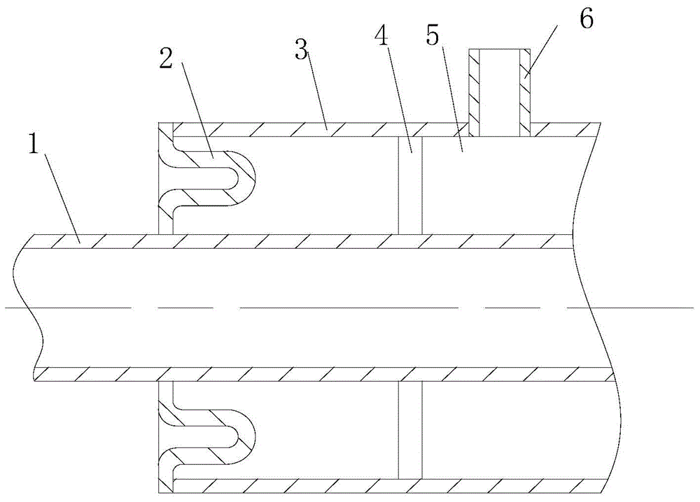
[0012] Such as figure 1 with figure 2 As shown, the vacuum insulated pipe of the present invention includes an inner pipe 1 and an outer pipe 3, the inner pipe 1 and the outer pipe 3 are coaxial, an inner pipe support 4 is provided between the inner pipe 1 and the outer pipe 3, and the outer wall of the inner pipe 1 has The outer tube 3 is welded with a vacuum nozzle 6 perpendicular to it, and the vacuum nozzle 6 is used to draw a high vacuum. Generally, the vacuuming time is about 8 days, and the vacuum leak is detected by a helium mass spectrometer leak detector.

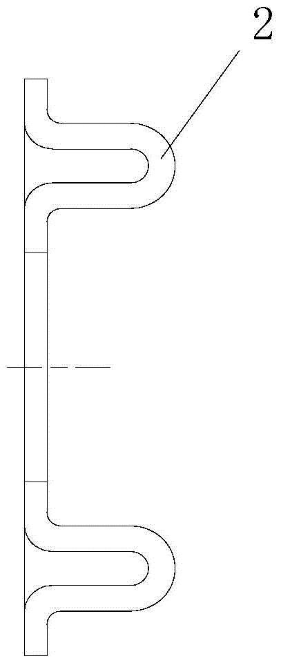
[0013] The vacuum insulation tube end plate 2 is vertically welded between the inner tube 1 and the outer tube 3 . A groove is arranged inside the end plate 2 of the vacuum heat insulating tube. The vacuum insulation tube end plate 2 is U-shaped. The inner tube 1, the outer tube 3, and the vacuum insulation tube end plate 2 are made of austenitic stainless steel. The end plate 2 of the vacuum heat insulating ...


PUM


Abstract

The invention relates to the field of pipeline conveying, in particular to a vacuum heat insulation tube. The vacuum heat insulation tube comprises an inner tube, an outer tube and a vacuum heat insulation tube end plate, wherein the inner tube is coaxial to the outer tube; an internal tube support is arranged between the inner tube and the outer tube; the outer wall of the inner tube is wound with multiple layers of heat insulation materials; a vacuum nozzle which is vertical to the outer tube is welded on the outer tube; the vacuum heat insulation tube end plate is vertically fixed between the inner tube and the outer tube. By adopting the vacuum heat insulation tube end plate, the vacuum heat insulation tube is easy to manufacture, is low in manufacturing cost, and has high practicability; meanwhile, the service life of the vacuum heat insulation tube is prolonged effectively.

Description

technical field [0001] The invention relates to the field of pipeline transportation, in particular to a vacuum insulation pipe. Background technique [0002] In supporting equipment such as pressure vessels and pressure pipelines, especially in similar low-temperature places such as LNG stations and gas filling stations, vacuum insulated pipes are commonly used low-temperature pipelines, and their main function is to effectively reduce the absorption of liquids during transportation. Thermal evaporation reduces the loss of LNG. Extremely strict requirements must be met in terms of thermal insulation, and the design temperature of -196°C ~ +60°C must be met. The vacuum insulation tube is designed according to the double-layer vacuum structure. The inner tube is used to store low-temperature liquid LNG, and its outer wall is wrapped with multiple layers of thermal insulation material, which has super thermal insulation performance. At the same time, the jacket (the space be...

Claims


Application Information

Patent Timeline
Patent Type & Authority Applications(China)
IPC IPC(8): F16L59/065F16L51/00
CPCF16L59/065F16L51/00
Inventor 吴慧娟郑安力梁宝明张永
Owner TERRENCE ENERGY
Learn More