Engine oil pump of internal combustion engine

A technology of oil pump and internal combustion engine, applied in the direction of lubricating pump, mechanical equipment, engine components, etc., can solve the problems of unsatisfactory sealing method, shorten the service life of internal combustion engine, reduce lubrication quality, etc., to ensure smooth delivery and lubrication quality, avoid oil Insufficient pressure to avoid the effect of oil foaming

Active Publication Date: 2015-04-01
重庆渝安淮海动力有限公司
View PDF8 Cites 3 Cited by
  • Summary
  • Abstract
  • Description
  • Claims
  • Application Information

AI Technical Summary

Problems solved by technology

[0002] The oil pump of the internal combustion engine is the power source of the oil pressure and flow in the lubrication system. It ensures the oil pressure and flow required for the lubrication of the internal combustion engine; the existing oil pump is divided into gear type, rotor type, vane type and plunger type in terms of structure. type, but the oil pumping principle is similar; the existing internal combustion engine oil pump generally includes a pump casing and a pump cover, and the pump casing is provided with an oil inlet chamber, an oil outlet chamber and corresponding oil passages. A low-pressure area is formed, and the oil outlet cavity forms a high-pressure area, and the oil in the oil pan is sent to the oil filter and each lubricating oil passage to lubricate the main moving parts of the internal combustion engine and filter the oil; the pump shell and The end faces of the pump cover are pressed against each other to seal the functional chambers on the pump casing; however, this sealing method is not ideal, especially for the oil inlet chamber in the low-pressure area, because there is no special seal on the pump casing to seal the oil inlet chamber. The structure causes the air to be sucked into the oil chamber, which not only causes insufficient oil pressure and affects the delivery, but also mixes the air with the oil to make the oil foam and reduce the lubrication quality, directly weakening the overall performance of the internal combustion engine, especially shortening the use of the internal combustion engine Life and reduced energy savings

Method used


Image

  • Engine oil pump of internal combustion engine

Examples


Embodiment Construction

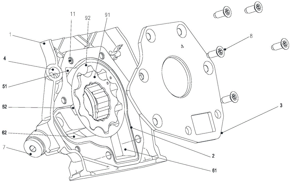
[0018] figure 1 It is a structural schematic diagram of the present invention, as shown in the figure: the internal combustion engine oil pump of this embodiment includes a pump casing 1 provided with an oil inlet chamber, and the pump casing 1 is also provided with a sealing groove for sealing the oil inlet chamber 2. The internal combustion engine oil pump also includes a pump cover 3 that is detachably connected to the pump casing 1, and the pump cover 3 presses and seals the sealing groove 2; the sealing groove 2 is preferably formed by casting; the pump casing 1 There is a sealing groove 2 specially used to seal the oil inlet cavity. The sealing groove 2 can effectively prevent air from being sucked into the oil cavity through oil seals, water seals or sealing rings, so as to avoid insufficient oil pressure and oil foaming. Ensure the smooth delivery and lubricating quality of engine oil, so that the overall performance of the internal combustion engine can be strengthene...


PUM


Abstract

The invention discloses an engine oil pump of an internal combustion engine. The engine oil pump comprises a pump shell provided with an oil inlet cavity, wherein a sealing groove for sealing the oil inlet cavity is also formed in the pump shell; an oil outlet and an oil outlet cavity I communicated with the oil outlet are formed in the pump shell; the sealing groove is an oil groove which is communicated with the oil outlet cavity I and is filled with high-pressure engine oil to realize oil sealing. According to the engine oil pump of the internal combustion engine, the sealing groove special for sealing the oil inlet cavity is formed in the pump shell, so that air can be effectively prevented from being sucked into the oil inlet cavity in an oil sealing way through the sealing groove, the situations of insufficient engine oil pressure and foaming of engine oil are avoided, and successful conveying of engine oil and the lubricating quality are ensured. Therefore, the overall performance of the engine is enhanced, the service life of the engine is prolonged, and the energy-saving effect is enhanced.

Description

technical field [0001] The invention relates to an internal combustion engine component, in particular to an internal combustion engine oil pump. Background technique [0002] The oil pump of the internal combustion engine is the power source of the oil pressure and flow in the lubrication system. It ensures the oil pressure and flow required for the lubrication of the internal combustion engine; the existing oil pump is divided into gear type, rotor type, vane type and plunger type in terms of structure. type, but the oil pumping principle is similar; the existing internal combustion engine oil pump generally includes a pump casing and a pump cover, and the pump casing is provided with an oil inlet chamber, an oil outlet chamber and corresponding oil passages. A low-pressure area is formed, and the oil outlet cavity forms a high-pressure area, and the oil in the oil pan is sent to the oil filter and each lubricating oil passage to lubricate the main moving parts of the inte...

Claims


Application Information

Patent Timeline
Patent Type & Authority Applications(China)
IPC IPC(8): F16N13/00F01M1/02
Inventor 段伟李金印姜小林钟贤
Owner 重庆渝安淮海动力有限公司
Why Eureka
Try Eureka