
LED (light emitting diode) panel lamp and frame thereof

A frame and frame profile technology, applied in the field of LED panel lights and their frames, can solve problems such as large luminous effect differences and quality problems, inability to ensure gaps, difficult insertion and other problems, to ensure optical effects and consistency, and simple splicing structure Reasonable and convenient assembly and debugging effect

Active Publication Date: 2015-04-01
ANHUI ZERUN OPTOELECTRONICS
View PDF7 Cites 2 Cited by
  • Summary
  • Abstract
  • Description
  • Claims
  • Application Information

AI Technical Summary

Problems solved by technology

In the above structure, the LED circuit board (light bar) can only be inserted from the frame groove at one end of the frame profile to the other end, which is difficult to insert and install, and a large assembly gap must be left, otherwise it will cause failure to assemble or damage the light bar , a large assembly gap will lead to large differences in luminous effects and quality problems, and it is also impossible to ensure the gap between the light incident surface on the side of the light guide plate and the LEDs on the LED light bar, nor can it ensure the center height of the LEDs on the LED light bar Consistent with the center height of the side incident light surface of the light guide plate

Method used


Image

  • LED (light emitting diode) panel lamp and frame thereof
  • LED (light emitting diode) panel lamp and frame thereof
  • LED (light emitting diode) panel lamp and frame thereof

Examples


Embodiment Construction

[0029] Embodiments of the present invention are described in detail below, examples of which are shown in the drawings, wherein the same or similar reference numerals designate the same or similar elements or elements having the same or similar functions throughout. The embodiments described below by referring to the figures are exemplary and are intended to explain the present invention and should not be construed as limiting the present invention.

[0030] In describing the present invention, it should be understood that the terms "center", "longitudinal", "transverse", "length", "width", "thickness", "upper", "lower", "front", " The orientations or positional relationships indicated by "rear", "left", "right", "vertical", "horizontal", "top", "bottom", "inner", "clockwise", "counterclockwise" are based on the attached The orientation or positional relationship shown in the figure is only for the convenience of describing the present invention and simplifying the description...


PUM


Abstract

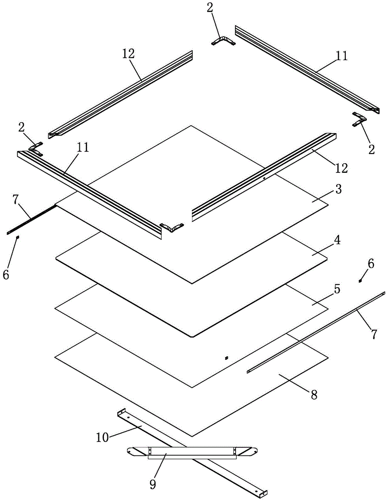
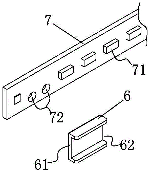
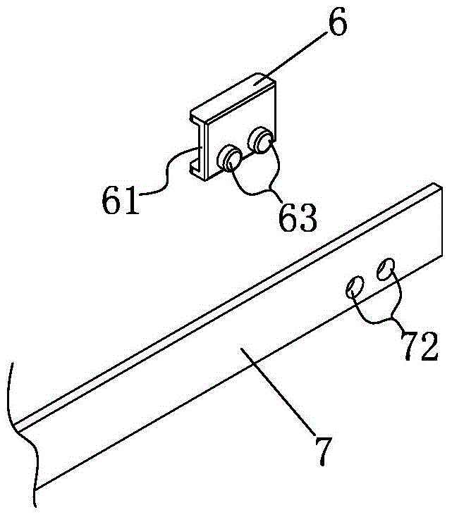
The invention discloses an LED (light emitting diode) panel lamp and a frame thereof. The frame is spliced by two first frame section bars and two second frame section bars through four corner joints; the two second frame section bars are arranged oppositely, each corner joint is provided with a first plugging arm and a second plugging arm; the root part of each first plugging arm is connected with the corresponding second plugging arm, the head part of each first plugging arm is inserted into a first jack of the corresponding first frame sections bar, the top of each first plugging arm and the top inner wall of the corresponding first jack are provided with at least three contacts which are not in the same line, and the bottom of each first plugging arm and the bottom inner wall of the corresponding first jack are provided with at least three contacts which are not in the same line; the head part of each second plugging arm is inserted into a second jack of the corresponding second section bar, and is connected with the same method; the root part of each first plugging arm is larger than the head part of the first plugging arm, and the root part of each second plugging arm is larger than the head part of the second plugging arm. The LED panel lamp and the frame thereof adopting the technical scheme have the advantages that the structure is simple and reasonable, the assembly and debugging are convenient, the yield is high, and the productivity is high.

Description

technical field [0001] The invention belongs to the field of lighting fixtures, in particular to an LED panel light and its frame. Background technique [0002] Light-emitting diodes, as light-emitting devices, are more and more widely used in the field of lighting fixtures. LED has the advantages of low power consumption, high luminous intensity, energy saving and environmental protection. Compared with traditional lamps such as incandescent lamps and fluorescent lamps, LEDs are more and more preferred by users. In the field of home lighting, LED ceiling lamps have become more and more popular. [0003] In the prior art, the LED panel light using the light guide plate is provided with textures on one side of the light guide plate, such as silk screen texture, frosted texture or concave-convex texture, and a reflective layer is covered on the textured surface of the light guide plate, and then the surface of the light guide plate is covered with a reflective layer. The non...

Claims


Application Information

Patent Timeline
IPC IPC(8): F21S8/04F21V17/16F21Y101/02
CPCF21S8/03F21S8/04F21V17/16F21V17/164F21Y2101/00F21Y2103/10F21Y2115/10
Inventor 陈荣生陈和生陈耀卫张宏庭许正杭
Owner ANHUI ZERUN OPTOELECTRONICS
Learn More