Force sensor sensitivity coefficient impact calibration device and method

A sensitivity coefficient, force sensor technology, applied in the field of mechanics, can solve the problems of the load pulse width is difficult to break through the millisecond level, the shock load excitation is difficult to carry out, the load level is limited, etc., and achieves easy operation and maintenance, simple structure, and stability. good effect

Pending Publication Date: 2022-05-13
NORTHWESTERN POLYTECHNICAL UNIV
View PDF4 Cites 0 Cited by
  • Summary
  • Abstract
  • Description
  • Claims
  • Application Information

AI Technical Summary

Problems solved by technology

[0005] The vibration calibration device mainly excites the load through the exciter and the counterweight, and when the counterweight is too large, it is easy to cause a large calibration error due to eccentricity or off-axis; the air bearing can reduce the influence of the axis deviation to a certain extent , but its cost is too high, so in practical engineering applications, the magnitude of the load excited by the vibration calibration device is limited
The load excitation method based on mass collision, due to the limitation of the collision time, especially the application of the waveform shaper, makes it difficult for the load pulse width to exceed the millisecond level
Therefore, the load magnitude excited by the current force sensor dynamic calibration device is usually a pulse width of 10 1 ms magnitude, amplitude 10 4 N order of magnitude, it is difficult to carry out shock load excitation with narrower pulse width and higher amplitude such as explosion

Method used


Image

  • Force sensor sensitivity coefficient impact calibration device and method
  • Force sensor sensitivity coefficient impact calibration device and method
  • Force sensor sensitivity coefficient impact calibration device and method

Examples


Embodiment Construction

[0056] The present invention will be further described below in conjunction with the accompanying drawings and embodiments.

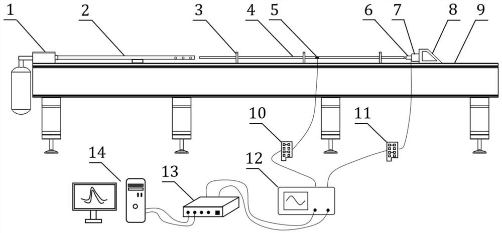
[0057] In view of the limitation of the load excitation range of the current force sensor sensitivity coefficient dynamic calibration device, the present invention establishes a relatively existing calibration device based on the Hopkinson bar that can excite a narrower pulse width (10 -1 ms order), higher amplitude (10 5 The invention discloses a method and device for calibrating the sensitivity coefficient of a force sensor for an impact force load of N order of magnitude).

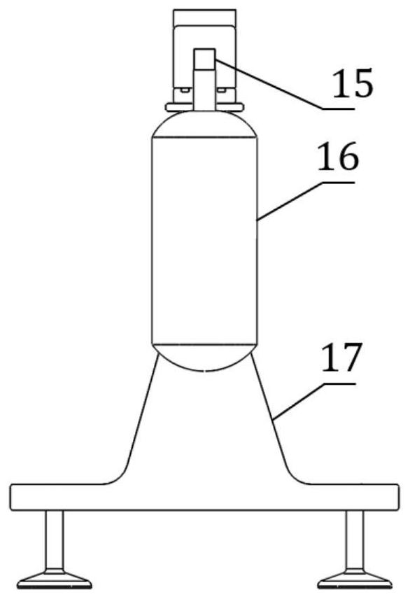
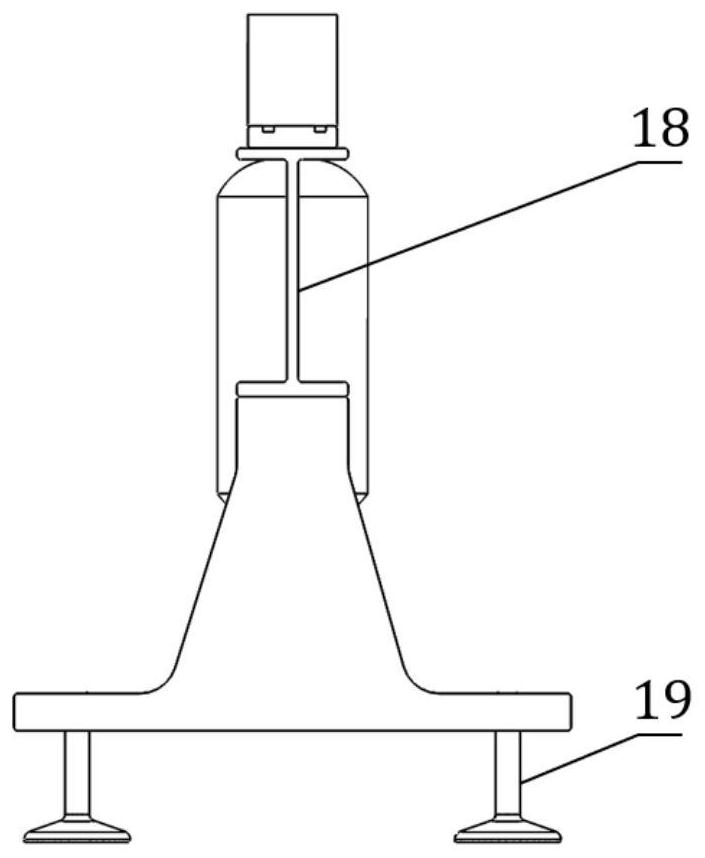
[0058] A force sensor sensitivity coefficient impact calibration device, including quick release valve 1, gun barrel 2, rod support 3, Hopkinson rod 4, impact force sensor 6, anvil 7, anvil tooling 8, aluminum alloy table 9, high pressure cylinder connected Mechanism 15, high-pressure cylinder 16, support seat 17, I-beam 18, leveling seat 19, bullet and measuring system;

[005...


PUM


Abstract

The invention discloses a force sensor sensitivity coefficient impact calibration device and method. The force sensor sensitivity coefficient impact calibration device comprises a quick release valve, a gun barrel, a rod support, a Hopkinson rod, an impact force sensor, an anvil block, an anvil block tool, an aluminum alloy table top, a high-pressure air cylinder communication mechanism, a high-pressure air cylinder, a supporting seat, an I-shaped steel beam, a leveling seat, a bullet and a measuring system. High-pressure gas is adopted to drive a bullet to impact a Hopkinson rod, an impact load is excited in the rod and spread along the rod, finally, the impact load is applied to a force sensor constrained by axial displacement, and impact calibration of the sensitivity coefficient of the force sensor is achieved through a measuring system. According to the dynamic calibration device, the load excitation range of an existing dynamic calibration device for the sensitivity coefficient of the force sensor is expanded, the pulse width of an excited impact force load can be reduced to 10-1ms magnitude, meanwhile, the amplitude is improved to 105N magnitude, and meanwhile, the dynamic calibration device is simple in structure, convenient to assemble and debug, good in stability and easy to operate and maintain.

Description

technical field [0001] The invention belongs to the technical field of mechanics, and in particular relates to a sensitivity coefficient shock calibration device and method. Background technique [0002] With the development of aerospace and national defense technology, various types of equipment face increasingly harsh and complex load environments during their service. Short duration (10 -1 ms level), high amplitude (10 5 N level) impact load has become an important factor that threatens the safety and stability of the system structure. Being able to accurately measure the impact load of the bearing structure under real working conditions or simulate real working conditions has important guiding significance for the reliability design and strength checking of structures. [0003] In actual engineering, dynamic / impact force sensors are usually used to measure the impact load, and the key prerequisite to ensure the validity of the measurement results is the accurate calib...

Claims


Application Information

Patent Timeline
IPC IPC(8): G01L27/00G01L25/00G01L9/04
CPCG01L27/005G01L25/00G01L9/04Y02E30/30
Inventor 王清华高猛郭伟国
Owner NORTHWESTERN POLYTECHNICAL UNIV
Why Eureka
Try Eureka