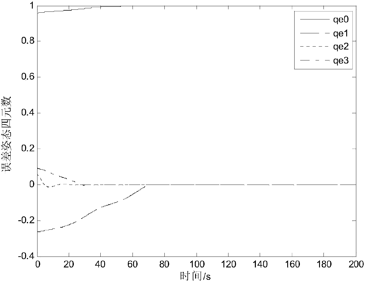
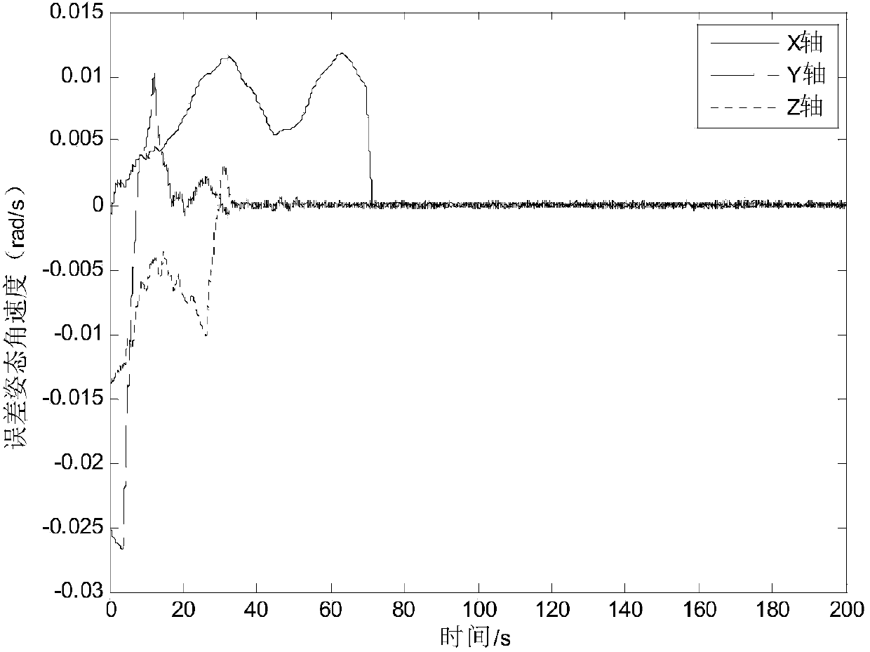
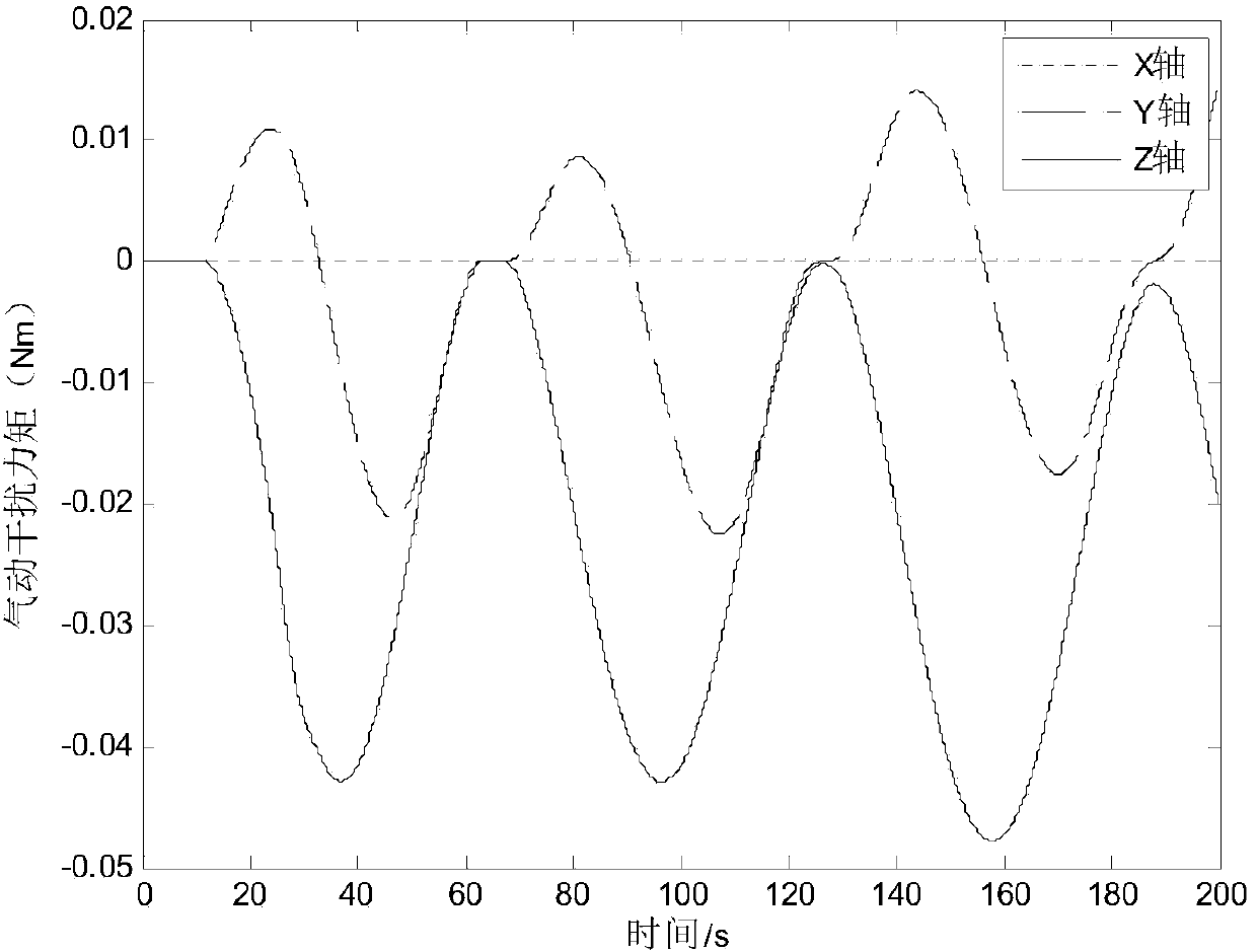
Low-orbit flexible satellite attitude tracking control method based on sliding-mode observer

A sliding mode observer, flexible satellite technology, applied in attitude control, adaptive control, general control system and other directions, can solve the problem of low accuracy of satellite attitude tracking control

Active Publication Date: 2015-04-01
HARBIN INST OF TECH
View PDF3 Cites 20 Cited by
  • Summary
  • Abstract
  • Description
  • Claims
  • Application Information

AI Technical Summary

Problems solved by technology

[0003] The purpose of the present invention is to solve the problem of low satellite attitude tracking control accuracy caused by the large aerodynamic disturbance moment and the vibration of t...

Method used


Image

  • Low-orbit flexible satellite attitude tracking control method based on sliding-mode observer
  • Low-orbit flexible satellite attitude tracking control method based on sliding-mode observer
  • Low-orbit flexible satellite attitude tracking control method based on sliding-mode observer

Examples


specific Embodiment approach 1

[0026] The low-orbit flexible satellite attitude tracking control method based on the sliding mode observer of the present embodiment, the low-orbit flexible satellite attitude tracking control method is realized through the following steps:

[0027] Step 1: Establish the geocentric inertial coordinate system OX I Y I Z I and satellite body coordinate system OX b Y b Z b ;

[0028] Step 2: Define the modal vibration state Thus, the attitude dynamics equation of the flexible satellite is expressed as a state space expression; where, Represents the modal vibration velocity, δ represents the rigid-flexible coupling matrix, ω bI Indicates the current attitude angular velocity;

[0029] Step 3. Determine the interference signal received by the observer according to the nature of the orbital environment of the satellite and the relational expression of the angular velocity-induced flexural vibration , and the observer sliding mode term gain ρ satisfies: ρ≥sup||d||; where...

specific Embodiment approach 2

[0036] The difference from the specific embodiment 1 is that the attitude tracking control method of the low-orbit flexible satellite based on the sliding mode observer in this embodiment, the earth-centered inertial coordinate system OX described in step 1 I Y I Z I , the coordinate origin of the geocentric inertial coordinate system is the earth's center of mass, OZ I axis along the direction of the earth's rotation axis pointing north, OX I The axis points to the direction of the vernal equinox, OY I Axis and OX I Shaft and OZ I The axes form a right-handed Cartesian coordinate system;

[0037] Satellite body coordinate system OX described in step 1 b Y b Z b , the coordinate origin of the satellite body coordinate system is the center of mass of the satellite, OX b Axis, OY b Shaft and OZ b The axis is fixedly connected with the star, and makes the OX of the coordinate axis b Axis, OY b Shaft and OZ b axis coincides with the satellite's main axis of inertia. ...

specific Embodiment approach 3

[0038] The difference from Embodiment 1 or Embodiment 2 is that the attitude tracking control method of the low-orbit flexible satellite based on the sliding mode observer in this embodiment, as described in step 2, rewrites the dynamic equation of the attitude of the flexible satellite into a state space expression: x · = Ax + Bu + Bf + BT d y = Hx ; In the formula,

[0039] x is the state quantity of the system and x=(η T ψ T ω bI T ) T ,

[0040] η represents the modal vibration displacement,

[0041] A...


PUM


Abstract

The invention discloses a low-orbit flexible satellite attitude tracking control method based on a sliding-mode observer, relates to a low-orbit flexible satellite attitude tracking control method based on a sliding-mode observer, and aims at solving the problems that an existing low-orbit flexible satellite is low in satellite attitude tracking control accuracy due to relatively large aerodynamic interference torque and vibration of flexile components. The low-orbit flexible satellite attitude tracking control method based on the sliding-mode observer comprises the following steps: building a geocentric inertial coordinate system and a satellite body coordinate system; building a state space expression, and determining an upper bound of an interference signal received by the observer; solving a gain matrix of the observer, a matching matrix of the observer and a Lyapunov equation matrix variable; observing to obtain an estimated mode vibration velocity value of the sliding-mode observer and an estimated mode vibration state value of the sliding-mode observer; rewriting a kinetic equation of a flexible satellite attitude into an error attitude tracking control model; determining a sliding-mode term gain of the control law, and carrying out tracking control on the error attitude tracking model by adopting the siding-mode control law according to measured satellite attitude quaternion, attitude angular velocity information and estimated mode quantity value. The low-orbit flexible satellite attitude tracking control method is applied to satellite attitude tracking control.

Description

technical field [0001] The invention relates to a low-orbit flexible satellite attitude tracking control method based on a sliding mode observer. Background technique [0002] With the development of satellite attitude control technology, the requirements for satellite attitude control accuracy are getting higher and higher, especially for satellites with optical cameras as payloads, the payload has extremely high requirements for ground pointing accuracy. For this type of satellites, in order to improve the accuracy of optical imaging, they often choose low-orbit operation. Compared with mid-orbit satellites, low-orbit satellites are more affected by the aerodynamic moment, and the aerodynamic moment varies with the satellite attitude. The change will have a great impact on the accuracy of satellite attitude control. Therefore, the influence of aerodynamic disturbance torque must be considered when designing a high-precision satellite attitude control method. In addition, ...

Claims


Application Information

Patent Timeline
IPC IPC(8): G05D1/08G05B13/04
Inventor 易涛陈雪芹耿云海曾奎李冬柏王峰张刚叶东
Owner HARBIN INST OF TECH
Why Eureka
Try Eureka