
Manufacturing method for measurement clamp of steering column based on 3D printing technology

A measurement fixture and 3D printing technology, applied in the direction of digital output to printing unit, input/output process of data processing, instruments, etc., can solve the problems of affecting measurement results, poor installation repeatability, inconsistency, etc., and achieve good installation repeatability , Improve the production quality, the effect of precise fit

Inactive Publication Date: 2015-04-01
JIANGXI HONGDU AVIATION IND GRP
View PDF4 Cites 3 Cited by
  • Summary
  • Abstract
  • Description
  • Claims
  • Application Information

AI Technical Summary

Problems solved by technology

The driving rod measurement point is mainly designed with ergonomics, which is an irregular surface. The traditional driving rod measurement fixture generally adopts manual sampling and manual positioning of the driving rod measurement point to design the driving rod measurement fixture. The defects in this way: the measurement fixture Inaccurate fit with the steering column, inaccurate positioning of the measurement point of the steering column, and poor repeatability and inconsistency of the installation, seriously affect the measurement results, resulting in poor production quality of the steering column measurement fixture

Method used


Image

  • Manufacturing method for measurement clamp of steering column based on 3D printing technology

Examples


Embodiment Construction

[0016] In order to make the technical means, creative features, goals and effects achieved by the present invention easy to understand, the present invention will be further described below in conjunction with specific illustrations.

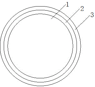
[0017] see figure 1 The driving rod measurement fixture includes the driving rod 1, the silicone bushing 2 and the metal shell 3. In order to prevent the steering rod 1 from being scratched during the installation of the measuring fixture, the driving rod measuring fixture includes the metal shell 3 and the silicone bushing 2; The production method is: use 3D printing technology to scan the measuring point of the driving rod (that is, point T) to obtain point cloud data, and obtain the 3D data of the driving rod measuring fixture after processing such as matching and smoothing, so as to carry out 3D printing of the driving rod measuring fixture production; the specific steps are as follows:

[0018] 1) In the image data software in the computer...


PUM


Abstract

The invention discloses a manufacturing method for a measurement clamp of a steering column based on 3D printing technology. In order to prevent the steering column from rubbing in the installing process of the measurement clamp, the measurement clamp of the steering column is provided with a soft material and a metal shell. The 3D printing technology is used for scanning the measurement point of the steering column to obtain the origin point cloud data, the point cloud data of the soft material and the metal shell is obtained on the basis of the origin point cloud data, and the three-dimensional data of the measurement clamp of the steering column is obtained after the processing of matching, firing and the like, so that the 3D printing production of the measurement clamp of the steering column is performed. The origin point cloud data is obtained by scanning the measurement point of the steering column through the 3D printing, the point cloud data of the soft material and the metal shell is obtained on the basis of the origin point cloud data, the fitting degree of the measurement clamp is precision after the steering column is partially and reversely restored, and the measurement point of the steering column is positioned accurately. In addition, the installing repeatability is good and the front and back are uniform, so the production quality of the measurement clamp of the steering column is effectively improved.

Description

technical field [0001] The invention relates to the technical field of manufacturing an aircraft steering rod fixture, in particular to a method for manufacturing a steering rod measuring fixture based on 3D printing technology. Background technique [0002] During the flight operation of the aircraft, the pilot control device is an important part for the pilot to control the aircraft, and its characteristic parameters directly affect the flight quality and safety, so it needs to be checked regularly. Among them, the control stick is an important device for the pilot to control the aircraft to achieve pitch and roll flight. In order to ensure the accuracy of the regular inspection of the pilot's control device, it is necessary to install a test fixture at the measurement point of the control stick to measure the force and displacement of the control stick. parameter. The driving rod measurement point is mainly designed with ergonomics, which is an irregular surface. The tra...

Claims


Application Information

Patent Timeline
Patent Type & Authority Applications(China)
IPC IPC(8): G06F3/12
CPCG06F3/1208G06F3/128
Inventor 季亚玢江涛树秀志陈林黄祖丹张弛徐燕殷晓华谭磊武琳
Owner JIANGXI HONGDU AVIATION IND GRP
Learn More