
Method and device for compressing and storing indicator diagram data of oil pumping unit

A technology of data compression and dynamometer diagram, applied in database indexing, electrical digital data processing, structured data retrieval, etc., can solve problems such as high cost, slow processing speed, large amount of dynamometer diagram data, etc., and save capital cost , the effect of saving storage resources

Active Publication Date: 2015-04-01
PETROCHINA CO LTD
View PDF4 Cites 13 Cited by
  • Summary
  • Abstract
  • Description
  • Claims
  • Application Information

AI Technical Summary

Problems solved by technology

This method needs to deploy at least one database server in each operation area and install a set of relational database, each costing about 100,000 yuan
But there are still two problems in this storage method: (1) utilize relational database to carry out the processing of real-time data, its processing speed is much slower than real-time database, needs to carry out data conversion with data processing software SCADA connection, is unfavorable for real-time dynamic analysis; (2) The cost of this storage method is also very high. If calculated on the basis of 200 wells in each operation area, the investment for each operation is 100,000 yuan, and at least 100 million yuan is required for the full implementation of PetroChina.
[0005] The dynamometer data collected and stored in the prior art is large, and the cost of real-time database storage and relational database storage equipment is very high, which increases the production cost of oil field data storage and server storage resources, and also reduces the later data reading, Calling, synchronization and other processing speed

Method used


Image

  • Method and device for compressing and storing indicator diagram data of oil pumping unit
  • Method and device for compressing and storing indicator diagram data of oil pumping unit
  • Method and device for compressing and storing indicator diagram data of oil pumping unit

Examples


Embodiment Construction

[0026] In order to enable those skilled in the art to better understand the technical solutions in the present application, the technical solutions in the embodiments of the present application will be clearly and completely described below in conjunction with the drawings in the embodiments of the present application. Obviously, the described The embodiments are only some of the embodiments of the present application, but not all of them. Based on the embodiments in this application, all other embodiments obtained by persons of ordinary skill in the art without creative efforts shall fall within the scope of protection of this application.

[0027] In the existing implementation scheme, a load sensor and a displacement sensor can be installed on the pumping unit, and a set of dynamometer data can be collected in real time. The closed curve diagram formed, such as the dynamometer diagram showing the relationship between the suspension point load and displacement of the pumping...


PUM


Abstract

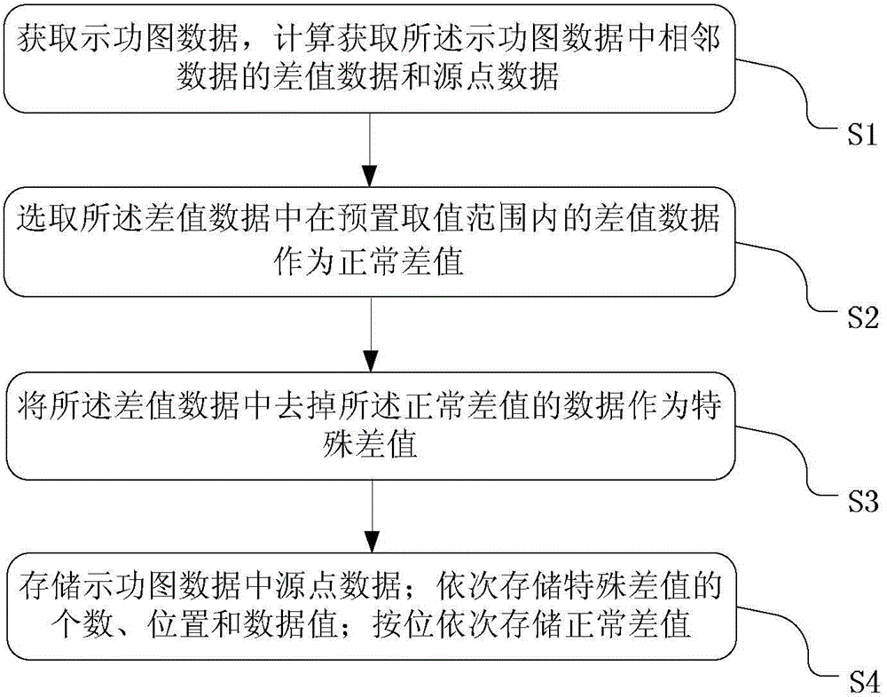
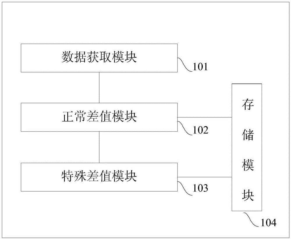
The invention provides a method and a device for compressing and storing indicator diagram data of an oil pumping unit. The method comprises the following steps: S1, acquiring the indicator diagram data, and calculating to acquire difference value data of adjacent data in the indicator diagram data; S2, selecting difference value data within a preset value range from the difference value data for serving as normal difference values; S3, using data from which the normal difference values are removed in the difference value data as special difference values; S4, storing source point data in the indicator diagram data; storing the quantity of the special difference values and the positions and data values of the special difference values in sequence; storing the data of the normal difference values in sequence according in a bitwise mode. By adopting the embodiment of the invention, the indicator diagram data can be stored in a real-time database in a non-destructive way, and the storage space and maintenance cost are saved.

Description

technical field [0001] The application belongs to the technical field of oil and gas production data processing, and in particular relates to a method and device for compressing and storing data of an indicator diagram of a pumping unit. Background technique [0002] At present, most of the oil wells used in the production of oil and gas fields on the continental shelf of our country are pumping wells. Real-time collection of production data on the pumping unit can form a pumping unit dynamometer diagram. Through computer processing and analysis of the dynamometer data, the pumping unit well can be remotely monitored, working condition diagnosis and industrial fluid production of the oil well. measure. Due to the high maturity of this technology, it can change the traditional production method, reduce labor costs, and improve production efficiency. In recent years, this technology has been rapidly developed and widely used in oil production. [0003] After the dynamometer ...

Claims


Application Information

Patent Timeline
IPC IPC(8): G06F17/30
CPCG06F16/22
Inventor 龚仁彬李金诺
Owner PETROCHINA CO LTD
Learn More