Preparation method of LED light source and preparation method of LED light-emitting module

A technology of LED light source and LED chip, applied in the direction of light source, electric light source, point light source, etc., can solve the problems of high material cost, time cost and labor cost, influence of lighting angle, etc., to reduce the speed of light decay and production cycle. and time cost, the effect of reducing cost

Active Publication Date: 2015-04-01
HANGZHOU HANGKE OPTOELECTRONICS
View PDF6 Cites 7 Cited by
  • Summary
  • Abstract
  • Description
  • Claims
  • Application Information

AI Technical Summary

Problems solved by technology

[0007] The above-mentioned preparation of LED light sources includes brackets and gold wires. There are many technological processes, material costs, time costs and labor costs are high, and the lighting angle is affected by the shape of the brackets.

Method used


Image

  • Preparation method of LED light source and preparation method of LED light-emitting module
  • Preparation method of LED light source and preparation method of LED light-emitting module
  • Preparation method of LED light source and preparation method of LED light-emitting module

Examples


Embodiment 1

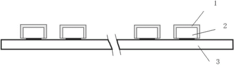
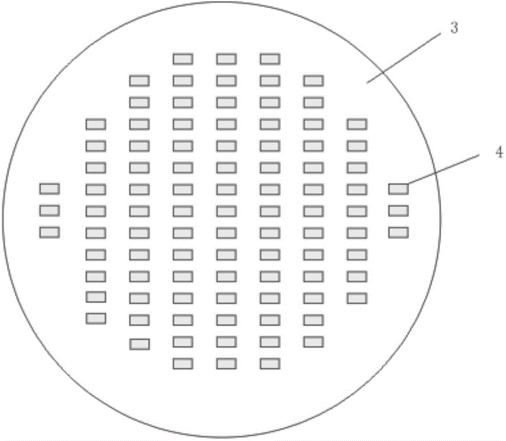
[0049] (1) The LED chip is a flip-chip blue LED chip, which is bonded to the PET film with UV glue on the surface at an equidistant distribution. The thickness of the film is 0.75mm, and the ultraviolet light is initially cured for 8s;

[0050] (2) On the surface of the LED chip (the main light-emitting surface and the four sides), spray a layer of organic silica gel water with a refractive index n=1.56, which is added with SiO with an average particle size of 10nm 2 particles, the SiO 2 Mass occupancy of particles in silicone water and SiO 2 7.5% of the total mass of the particles, the thickness of spraying is 0.5mm, and then placed in a 100°C oven for 25min pre-curing to prepare the isolation adhesive layer;

[0051] (3) Take out and spray a layer of silicone water mixed with fluorescent powder with a refractive index n=1.45. The silicone water mixed with fluorescent powder is composed of fluorescent powder (yellow fluorescent powder) and silicone water. The quality of the ...

Embodiment 2

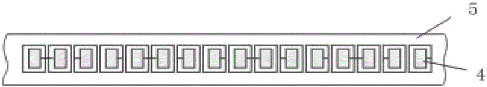
[0057] Arrange the LED white light sources prepared in Example 1 above in a series-parallel manner, and solder them on the PCB with solder paste to obtain an LED white light emitting module.

[0058] Such as image 3 As shown, the LED white light source 4 is soldered on the substrate 5 in series.

Embodiment 3

[0060] (1) The LED chip is a flip-chip blue LED chip, which is bonded to the PTFE film with UV glue on the surface at an equidistant distribution. The thickness of the film is 1.2mm, and the ultraviolet light is initially cured for 15s;

[0061] (2) On the surface of the LED chip (the main light-emitting surface and the four sides), spray a layer of organic silica gel water with a refractive index n=1.55, which is added with SiO with an average particle size of 15nm 2 particles, the SiO 2 Mass occupancy of particles in silicone water and SiO 2 10% of the total mass of the particles, the thickness of spraying is 0.6mm, and then placed in a 100°C oven for 35min pre-curing;

[0062] (3) Take out and spray a layer of silicone water mixed with fluorescent powder with a refractive index n=1.42. The silicone water mixed with fluorescent powder is composed of fluorescent powder (yellow fluorescent powder) and silicone water. The quality of the fluorescent powder is 100%. The compone...


PUM


Abstract

The invention discloses a preparation method of an LED light source and a preparation method of an LED light-emitting module. The preparation method of the LED light source comprises the following steps: bonding an LED chip on a PET film or a PTFE film with UV adhesive on the surface, and carrying out ultraviolet irradiation for initial curing; preparing an insulation rubber layer on the LED chip; then preparing a fluorescent colloid layer; using UV light to irradiate the PET film or the PTFE film to enable the UV adhesive on the surface to lose viscidity, and taking down the LED chip after encapsulation to obtain the LED light source. The LED light sources are arranged in a series-parallel connection mode, and are welded on a base plate, so that the LED light-emitting module is obtained. According to the preparation methods, in the aspect of material composition, supports and money are saved, the reliability is improved while the cost is reduced, the material cost can be reduced, the light-emitting angle is increased, the processing convenience is increased, and the production link is simplified. The position of fluorescent powder is far away from the chip through the insulation rubber layer, so that the thermal quenching and thermal efficiency of the fluorescent powder are reduced, and the lighting effect and long-term lumen maintenance are improved.

Description

technical field [0001] The invention relates to the field of LED chip packaging technology, in particular to a method for preparing an LED light source and an LED light-emitting module. Background technique [0002] A semiconductor light-emitting diode (LED) is a semiconductor that converts electrical energy into visible light. As the fourth-generation lighting source, LED has become one of the most promising fields in the 21st century. [0003] Usually, LED light sources are packaged with brackets, gold wires, phosphors, glue, etc. If it is necessary to form a suitable lighting fixture, multiple fully packaged LED light sources are used to form an array or module. From the bare LED chip to the LED lamp, the manufacturing process used in the entire production is very long. The complete packaging of a single LED light source must be completed first, and then soldered to the substrate as required, and then assembled into the final lamp. [0004] Existing LED light source par...

Claims


Application Information

Patent Timeline
Patent Type & Authority Applications(China)
IPC IPC(8): H01L25/075H01L33/48H01L33/50H01L33/64F21S2/00F21Y101/02
Inventor 严钱军高基伟徐小秋
Owner HANGZHOU HANGKE OPTOELECTRONICS
Why Eureka
Try Eureka