Pulling rope release system of small multi-shaft unmanned aerial vehicle

A technology of unmanned aerial vehicle and traction rope, which is applied in the field of small multi-axis unmanned aerial vehicle traction rope deployment system, can solve the problems of low degree of mechanized installation, hidden dangers of personal safety, and insufficient scheme, so as to improve the operation accuracy and construction effect, reducing the intensity of manual labor, and controlling the shooting angle

Inactive Publication Date: 2015-04-01
STATE GRID CORP OF CHINA +3
View PDF5 Cites 25 Cited by
  • Summary
  • Abstract
  • Description
  • Claims
  • Application Information

AI Technical Summary

Problems solved by technology

Because it is installed outdoors and in the field, it brings a lot of inconvenience to the installation, especially for non-professional installation teams, the degree of mechanized installation is low, the equipment is simple, the difficulty will be greater, and it will cause damage to the ecological environment
In the past, the power setting-out construction work was usually: 1. Manual setting-out, in mountainous areas, rivers, railways and other construction environments, the operation was extremely difficult and risky, the problem of compensation for young crops on the line was prominent, the intensity of personnel was high, and the cycle was long
2. The power parachute is released by two people in the air, one is the driver and the other is the releaser. The power parachute flies along the line with the traction rope, and puts down the rope when it reaches the designated tower; this method is costly and is affected by the wind Large; manned control in the air, there are potential personal safety hazards; high flying height requirements, resulting in poor throwing accuracy
[0003] In order to effectively solve the contradictions between various difficulties in ecological environment protection and engineering construction and stringing construction, there have been technical solutions in the prior art that use drones for traction and stringing, but most of the current technical solutions for drones are not enough. Perfect, there are many disadvantages, resulting in poor construction effect

Method used


Image

  • Pulling rope release system of small multi-shaft unmanned aerial vehicle
  • Pulling rope release system of small multi-shaft unmanned aerial vehicle

Examples


Embodiment Construction

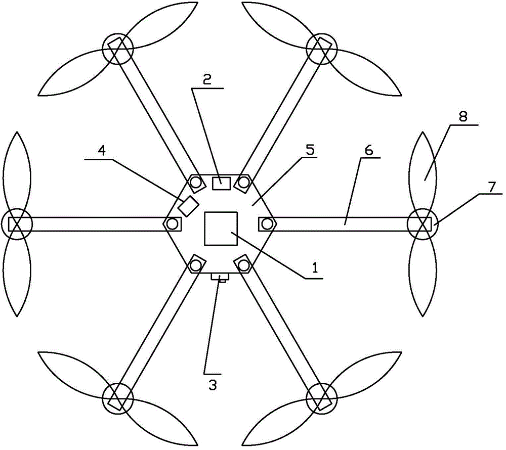
[0021] Examples, see figure 1 As shown, a kind of small-sized multi-axis unmanned aerial vehicle traction rope deployment system of the present invention comprises:

[0022] Multi-axis UAV, the multi-axis UAV is equipped with a control system 1 that can wirelessly receive remote control commands issued by the ground station and control the flight of the multi-axis UAV. The control system 1 specifically includes a GPS navigator, a receiving antenna, a power supply (The power supply is specifically a battery) and the master controller, the master controller receives the remote control command sent by the ground station through the receiving antenna;

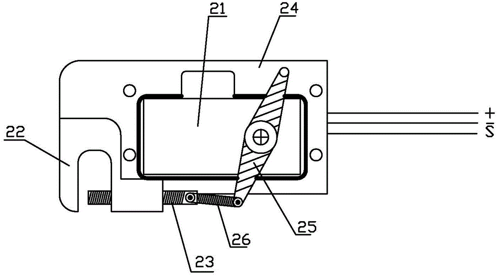
[0023] Lead wire unwinding device, the lead wire unwinding device includes a pay-off frame (not shown in the figure), a lead decoupling controller 2, a pay-off wheel is movable on the pay-off frame, and a traction rope is wound on the pay-off wheel. The pay-off frame is arranged on the ground, and the lead wire decoupling controll...


PUM


Abstract

The invention discloses a pulling rope release system of a small multi-shaft unmanned aerial vehicle, which comprises a multi-shaft unmanned aerial vehicle, a lead wire release device and a video monitor, wherein the multi-shaft unmanned aerial vehicle is equipped with a control system; the lead wire release device comprises a payoff rack wound with a pulling rope and a lead wire unhooking controller; the payoff rack is arranged on ground; the lead wire unhooking controller is mounted on the multi-shaft unmanned aerial vehicle and comprises a power mechanism and a locking mechanism; the power mechanism is connected with the control system of the multi-shaft unmanned aerial vehicle and with the locking mechanism to drive the locking mechanism to carry out locking or unlocking; one end of the pulling rope penetrates through the locking mechanism; the video monitor is mounted on the multi-shaft unmanned aerial vehicle and comprises an onboard camera and a real-time image transmission system; and the onboard camera and the real-time image transmission system are connected with the control system respectively. The system can carry out pay-off operation of the unmanned aerial vehicle in a high precision and controllability manner, so that the pay-off time is greatly saved, and a construction effect is significant.

Description

technical field [0001] The invention relates to a flight assisting tool, in particular to a traction rope deployment system for a small multi-axis UAV. Background technique [0002] Power wiring is an important facility to ensure the safety and quality of power supply and to distribute power reasonably. Because it is installed outdoors and in the field, it brings a lot of inconvenience to the installation, especially for non-professional installation teams, the degree of mechanized installation is low, the equipment is simple, the difficulty will be greater, and it will cause damage to the ecological environment. In the past, the power laying-out construction work was usually: 1. Manual laying-out, in mountainous areas, rivers, railways and other construction environments, the operation was extremely difficult and risky, the problem of compensation for young crops on the line was prominent, the intensity of personnel was high, and the cycle was long. 2. The power parachute ...

Claims


Application Information

Patent Timeline
Patent Type & Authority Applications(China)
IPC IPC(8): H02G1/02H04N7/18
Inventor 林火煅李郭然周晨晖陈育曙周志勇徐永进谢翊昕陈杰
Owner STATE GRID CORP OF CHINA
Why Eureka
Try Eureka