System and method for distributed power source of transformer substation

A distributed power supply and substation technology, applied in information technology support systems, electrical components, circuit devices, etc., can solve problems such as poor adaptability, difficult maintenance, and inconvenient operation of man-machine interface

Active Publication Date: 2015-04-01
SHANDONG LUNENG SOFTWARE TECH
View PDF4 Cites 3 Cited by
  • Summary
  • Abstract
  • Description
  • Claims
  • Application Information

AI Technical Summary

Problems solved by technology

[0003] (1) Each power supply monitoring device may be produced and installed by different suppliers, and professionals at different levels are also assigned to maintain it in management; because the overall design ideas of power supply devices of different manufacturers are inconsistent, there are technical disconnects and incoordination. Many problems are encountered during operation and debugging, and sometimes even affect the normal operation of the equipment, especially for smart substations and unattended substations, which have a greater impact;
[0004] (2) Due to the addition of system software requirements, function upgrades and the increase of measurement points, the software version of the distributed power system may not match the software version of the DC, AC and other power systems, resulting in obstacles to the interconnection between devices, which

Method used


Image

  • System and method for distributed power source of transformer substation
  • System and method for distributed power source of transformer substation
  • System and method for distributed power source of transformer substation

Examples


Embodiment Construction

[0078] The present invention will be further described below in conjunction with the accompanying drawings and embodiments.

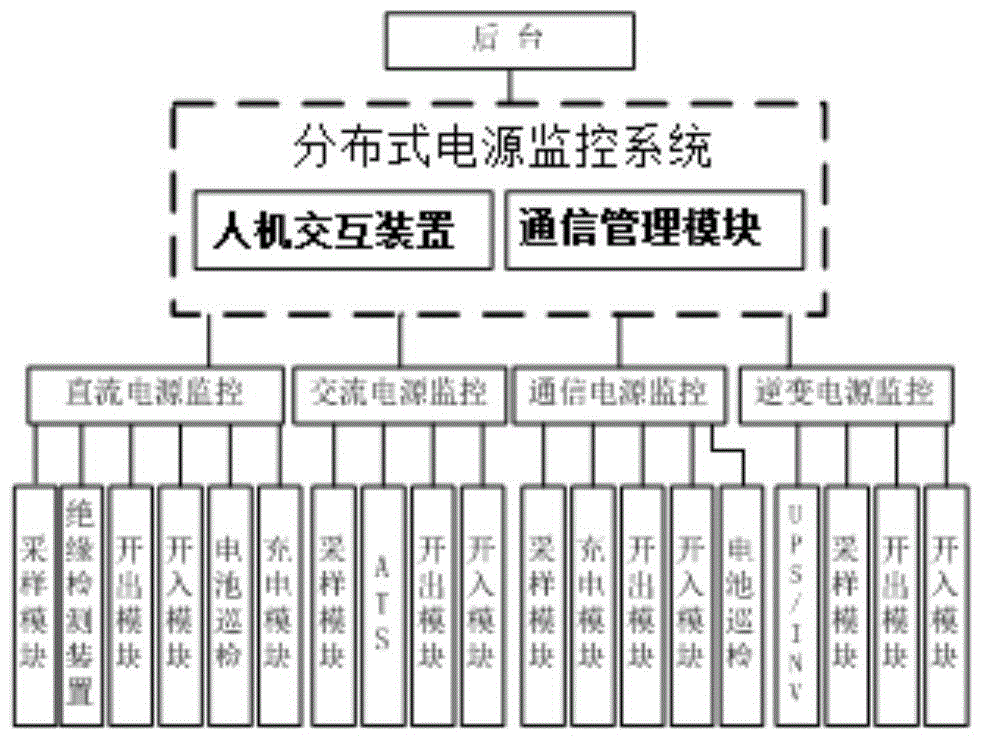
[0079] Such as figure 1 As shown, the distributed power monitoring device consists of two parts, a communication management module and a human-computer interaction module.

[0080] The communication management module completes functions such as real-time data collection, processing, alarm, and historical data storage; the human-computer interaction module performs data and status display, and human-computer interaction control functions.

[0081] Adopt hierarchical distributed structure. The power monitoring device (main monitoring) has a DC power monitoring subsystem, an AC power monitoring subsystem, a power monitoring subsystem, and an inverter monitoring subsystem. There can be multiple monitoring subsystems.

[0082] Under DC power monitoring, there are DC power system modules, sampling modules, insulation detection, input modules, output module...


PUM


Abstract

The invention discloses a system and method for a distributed power source of a transformer substation. The system comprises a distributed power source management system. The system for the distributed power source comprises a human-machine interaction device and a communication management module. The distributed power source management system is connected with a direct current power source monitoring sub-system, an alternating current power source monitoring sub-system, communication power source monitoring sub-systems and an inverter power source monitoring sub-system. The distributed power source management system comprises a self-adaption communication module and a dynamic configuration module, wherein the self-adaption communication module is in communication with the external environment through a port and is used for automatically identifying the communication management module to complete automatic identification of a configuration file, and the dynamic configuration module is used for dynamically displaying a wiring diagram and operation information of each monitoring sub-system according to configuration information. By means of the system and method for the distributed power source of the transformer substation, the configuration information of the transformer substation can be set by a user according to the specific demand, and an interface of the corresponding sub-system of the transformer substation is quickly displayed.

Description

technical field [0001] The invention relates to a substation distributed power supply system and method. Background technique [0002] Substation power consumption includes AC power sub-monitoring system, DC power monitoring system, inverter power monitoring system, communication power monitoring system, etc. The existing distributed power monitoring system has the following disadvantages: [0003] (1) Each power supply monitoring device may be produced and installed by different suppliers, and professionals at different levels are also assigned to maintain it in management; because the overall design ideas of power supply devices of different manufacturers are inconsistent, there are technical disconnects and incoordination. Many problems are encountered during operation and debugging, and sometimes even affect the normal operation of the equipment, especially for smart substations and unattended substations, which have a greater impact; [0004] (2) Due to the addition of...

Claims


Application Information

Patent Timeline
IPC IPC(8): H02J13/00
CPCY02E60/00Y04S10/16
Inventor 巩方彬张晓花张海龙曹淑英熊建成
Owner SHANDONG LUNENG SOFTWARE TECH
Why Eureka
Try Eureka