Quick release component for pin-joint latch hook

A technology of pin connection and locking hook, which is applied in the direction of casing/cabinet/drawer components, etc., can solve the problems of difficult design angle, high surface stress of contact parts, connection failure of chassis and mounting frame, etc., and achieve light weight , low cost, and the effect of improving connection reliability

Active Publication Date: 2015-04-01
AVIC NO 631 RES INST
View PDF3 Cites 5 Cited by
  • Summary
  • Abstract
  • Description
  • Claims
  • Application Information

AI Technical Summary

Problems solved by technology

[0004] However, in the process of processing and use, deviation and wear will inevitably occur, so the design angle is difficult to guarantee, resulting in excessive surface stress on the contact part, and even failure of the connection between the chassis and the mounting bracket

Method used


Image

  • Quick release component for pin-joint latch hook
  • Quick release component for pin-joint latch hook

Examples


Embodiment Construction

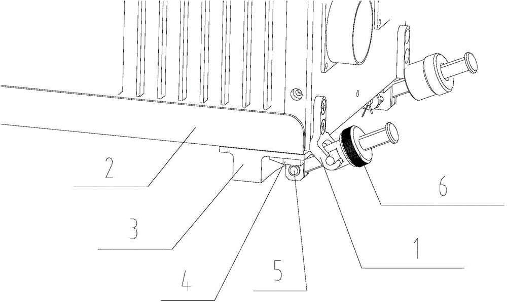
[0016] The present invention is described in detail in the following solutions to the accompanying drawings, as figure 2 Shown:

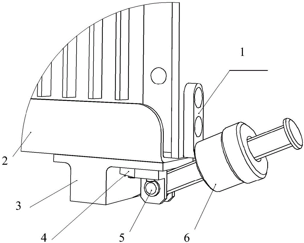
[0017] The chassis is connected to the connector through the guide. After the connection is completed, the chassis is placed on the guide. In order to prevent the chassis from sliding out of the guide due to vibration or to reduce reliability due to loose connection with the rear connector, the outer bottom of the guide A front base is installed, and a hinge is set on the front base for installing a locking device. The locking device is used to tighten the chassis, the connector and the guide through the front panel of the chassis. Therefore, the locking device needs to be applied to the chassis at the same time. Forces towards connectors and guides.

[0018] The pin-joint lock hook quick-release assembly is mainly composed of hinges, pins, pin-joint lock hooks, pin-joint front locking and other components. The pin-joint locking hook is fixedly a...


PUM


Abstract

The invention relates to a quick release component for a pin-joint latch hook. The quick release component for the pin-joint latch hook comprises a hinge, the pin-joint latch hook and a pin-joint front latch, wherein the pin-joint latch hook is fixedly arranged on a cabinet front faceplate; the pin-joint front latch is hinged to the hinge through a dowel; the pin-joint front latch is matched with the pin-joint latch hook; after the pin-joint front latch is tightened, the pin-joint latch hook is fastened towards a cabinet installation direction. According to the quick release component, the structure is simple; the fit clearance between the latch hook and a front latch component is effectively eliminated; the stress between the latch hook and the front latch component is prevented from being amplified; the reliability of structural interconnection between a cabinet and an installation rack is improved.

Description

technical field [0001] The invention relates to a fast-release assembly of a pin-connected locking hook, which is mainly used for locking an airborne case. Background technique [0002] At present, most of the airborne locking devices use A-type locking devices, such as figure 1 shown. Type A tightening device is composed of a front tightening assembly and a rear tightening assembly. The rear tightening assembly is realized by the cooperation of the taper pin on the mounting bracket and the pin sleeve on the chassis. The front tightening assembly is composed of hinges, pins, It is composed of the front locking assembly and the locking hook on the chassis. [0003] Due to the rigid connection between the hinge and the mounting frame, and the cooperation is realized through the surface fit between the front lock and the lock hook, and the current front lock is generally designed to rotate upwards by 20°, therefore, the lock hook and the two curved surfaces only have Surface...

Claims


Application Information

Patent Timeline
Patent Type & Authority Applications(China)
IPC IPC(8): H05K5/02
Inventor 焦超锋张丰华姜红明醋强一杨林
Owner AVIC NO 631 RES INST
Why Eureka
Try Eureka