
Surgery knotter

A knotter and surgery technology, applied in the field of surgical knotter, can solve the problems of damage to surrounding tissue, limitation of the angle and direction of the push knot, easy slippage of the suture, etc., and achieves the effect of high safety factor and high maneuverability

Inactive Publication Date: 2015-04-08
SHANGHAI PULMONARY HOSPITAL
View PDF6 Cites 2 Cited by
  • Summary
  • Abstract
  • Description
  • Claims
  • Application Information

AI Technical Summary

Problems solved by technology

[0006] However, the knot pushing angle and direction of the above-mentioned medical surgical knotter are limited, the suture is easy to slip off, and the knotting head of this structure is easy to accidentally damage the surrounding tissue during the knot pushing process.

Method used


Image

  • Surgery knotter
  • Surgery knotter

Examples


Embodiment Construction

[0022] In order to make the technical means, creative features, goals and effects achieved by the present invention easy to understand, the following embodiments will specifically illustrate the surgical knotter provided by the present invention in conjunction with the accompanying drawings.

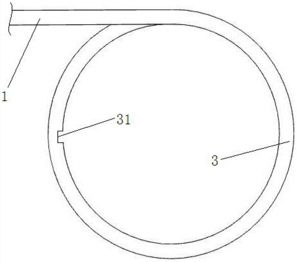
[0023] Such as figure 1 As shown, the surgical knotter provided in this embodiment. It includes: a rod body 1, a handle 2 arranged at the proximal end of the rod body 1, and a spiral knotting head 3 arranged at the far end of the rod body 1.

[0024] Specifically, the helical knotting head 3 spirals up one turn from the distal end of the rod body 1 . In this embodiment, the helical diameter of the helical knotting head 3 is 4 mm, and the pitch of the helical knotting head 3 is greater than the line width of the suture.

[0025] Such as figure 1 As shown, in order not to be affected by the operating angle during the knotting process, as a preferred technical solution, the rod body 1 is...


PUM


Abstract

The invention discloses a surgery knotter comprising a rod, a handle arranged at the near end of the rod and a spiral knotting head arranged at the far end of the rod. The spiral knotting head is arranged at the front end of the rod, so that peripheral tissue cannot be injured accidentally in the knot pushing process, and safety factor is high. Besides, a positioning groove used for positioning a suture line is arranged in the lower side wall of the rear of the spiral knotting head, so that the suture line cannot fall off during knot pushing, controllability is high.

Description

technical field [0001] The invention relates to medical instruments, in particular to a surgical knotter. Background technique [0002] Knot tying is a very important technique in surgical operations. Intraoperative hemostasis and suturing are inseparable from ligation. It can be said that knotting runs through the entire process of surgical operations. Whether the ligation is firm and reliable is closely related to the method of knotting, auxiliary equipment, and proficiency. The speed and quality of knotting are not only related to the length of operation time, but also affect the quality of the entire operation and the patient's postoperative recovery. [0003] The knotting methods of traditional surgical deep surgical sutures are basically divided into two types: manual knotting and forceps knotting. Due to the small field of vision and deep position, the fingers cannot enter the position that needs to be tied due to the manual knotting. Although holding the forceps to...

Claims


Application Information

Patent Timeline
IPC IPC(8): A61B17/04
CPCA61B17/04
Inventor 包敏伟姜格宁费苛
Owner SHANGHAI PULMONARY HOSPITAL
Learn More