First tread wedge joint plate

A joint and metatarsal wedge technology, applied in the field of medical devices, can solve problems such as low fusion rate, poor fixation stability, and increased incidence of osteoarthritis, and achieve the effect of increasing fusion rate, reducing stimulation, and facilitating early passive exercise

Inactive Publication Date: 2015-04-08
上海斯地德商务咨询中心
View PDF8 Cites 46 Cited by
  • Summary
  • Abstract
  • Description
  • Claims
  • Application Information

AI Technical Summary

Problems solved by technology

[0004] The technical problem to be solved by the present invention is: in order to overcome the prior art, some patients need to retain the cartilage of the first metatarsal cuneiform articular surface, the soft tissue of the first metatarsal cuneiform articular surface will be damaged by the

Method used


Image

  • First tread wedge joint plate
  • First tread wedge joint plate
  • First tread wedge joint plate

Examples


Embodiment 1

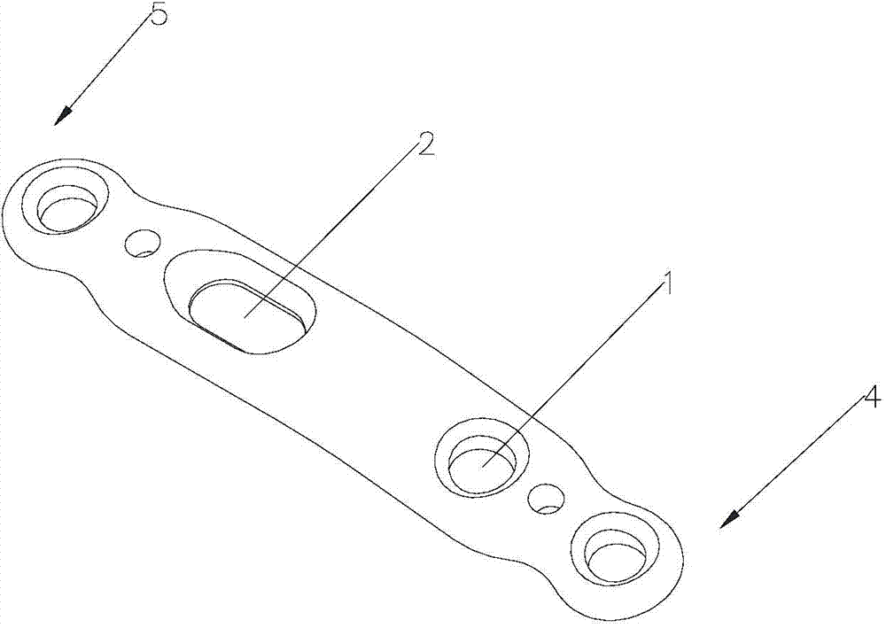
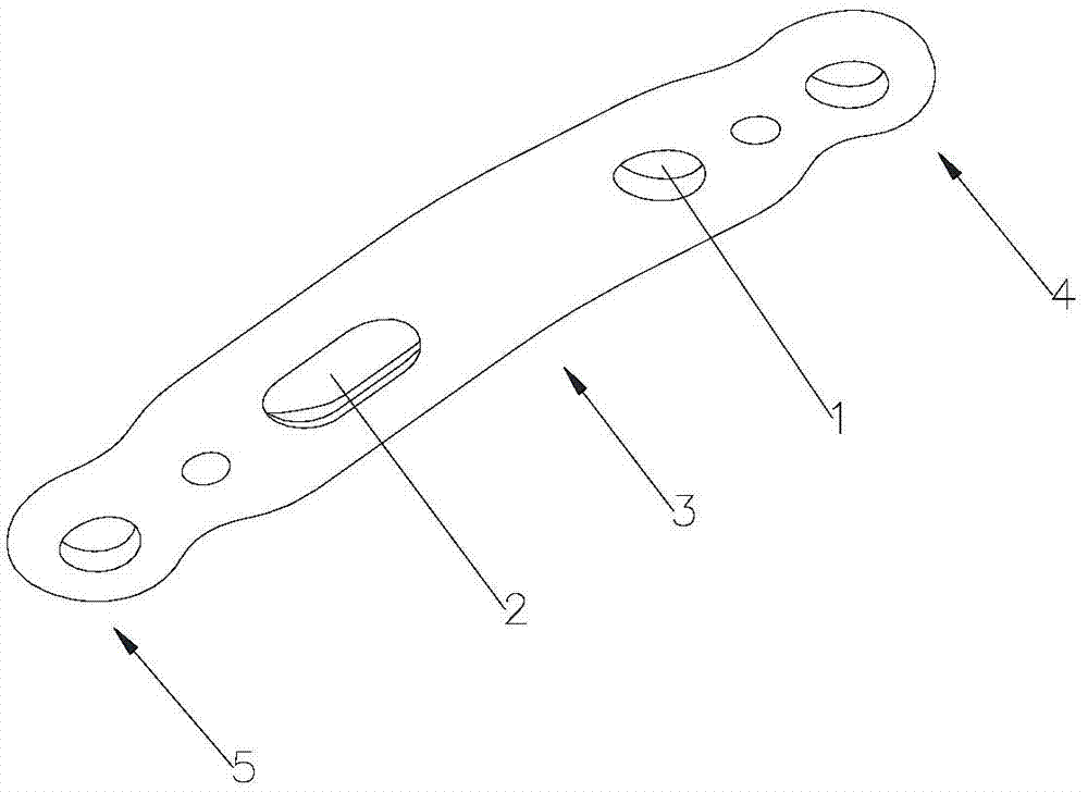
[0024] Such as figure 1 , figure 2 As shown, a first metatarsal wedge joint plate is a stainless steel plate with a thickness of 1.8mm, including a proximal end 4 and a distal end 5, the proximal end 4 is provided with two fixing holes 1, and the distal end 5 is provided with a fixing hole 1. There is also a sliding hole 2 on the first metatarsal cuneiform joint plate to facilitate the pressure between the bone blocks when the first metatarsal cuneiform joint is fused. The position of the sliding hole 2 is the same as when the joint plate is fixed on the first metatarsal bone and the medial cuneiform bone The position of the first metatarsal cuneiform joint corresponds to that of the first metatarsal cuneiform joint. The sliding hole 2 is located at the distal end 5 of the first metatarsal cuneiform joint. The surface morphology of the metatarsal bone and the medial cuneiform bone match, that is, the proximal end of the first metatarsal cuneiform joint plate 4 matches the sh...

Embodiment 2

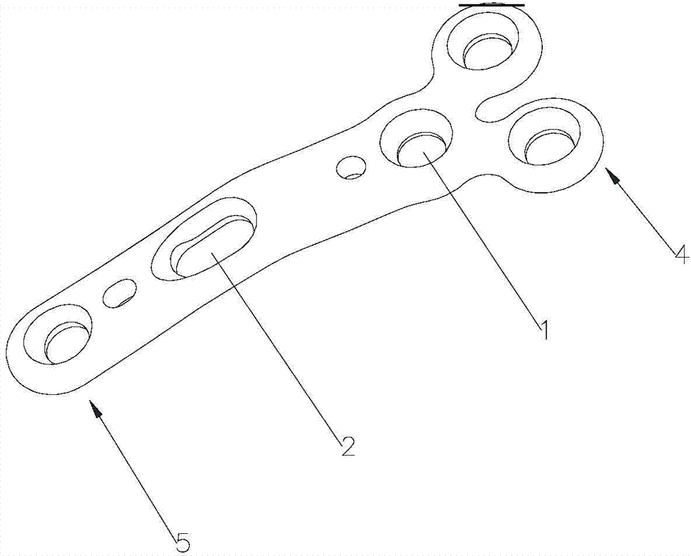
[0027] A first metatarsal wedge joint plate, which is a pure titanium plate with a thickness of 1.8 mm, comprising a proximal end 4 of the first metatarsal wedge joint plate and a distal end 5 of the first metatarsal wedge joint plate, and a proximal end 4 of the first metatarsal wedge joint plate There are three fixing holes 1, which are distributed in the shape of a character. The distal end 5 of the first metatarsal cuneiform joint plate is provided with a fixing hole 1, and the first metatarsal cuneiform joint plate is also provided with a joint between the bone blocks to facilitate the fusion of the first metatarsal cuneiform joint. Pressed sliding hole 2, the position of the sliding hole 2 corresponds to the position of the first metatarsal wedge joint when the first metatarsal wedge joint plate is fixed on the first metatarsal bone and the medial cuneiform bone, and the sliding hole 2 is located on the first metatarsal wedge joint plate 5 at the distal end; the spatial g...


PUM

PropertyMeasurementUnit
Thicknessaaaaaaaaaa

Abstract

The invention relates to the technical field of medical machinery, in particular to a first tread wedge joint plate. The first tread wedge joint plate comprises a plurality of fixing holes which are used for fixing the first tread wedge joint plate on a first metatarsal bone and an internal side wedge bone; a sliding hole which enables pressing between bones to be convenient during fusion of the first tread wedge joint is formed in the first tread wedge joint plate. According to the first tread wedge joint plate, tender moving of the first tread wedge joint surface is allowed when the bridge first tread wedge joint plate is fixed, namely, the first tread wedge joint surface gristle is kept and the joint is limited from moving; when the first tread wedge joint fuses the first tread wedge joint plate to be fixed, bone grafting after joint surface gristle is removed, pressing of the first tread wedge joint surface is achieved through a sliding hole at a far end of the first tread wedge joint plate, and accordingly the fusion rate is improved; the first tread wedge joint plate is in an anatomy type design, anatomical reduction is convenient, pre-bending of the first tread wedge joint plate during operation is not required, and the intensity of the first tread wedge joint plate is avoided from being influenced by bending during the operation.

Description

technical field [0001] The invention relates to the technical field of medical devices, in particular to a first metatarsal wedge joint plate. Background technique [0002] Since Albrecht first proposed fusion of the first metatarsal wedge joint to correct hallux valgus in 1911, and Lapidus reported the pathogenesis of hallux valgus in 1934 and the fusion of the first metatarsal wedge joint, the fusion of the first metatarsal wedge joint has gradually gained popularity. focus on. Lapidus proposed that the underlying pathogenesis of hallux valgus is adduction deformity of the first metatarsal and instability of the first sequence, and fusion of the first metatarsal wedge joint can correct the deformity in multiple planes, stabilize the first sequence, and have other hallux valgus orthopedic procedures advantages not available. In the following 20 years, Lapidus successively reported the long-term follow-up results of using this operation to correct moderate and severe hallu...

Claims


Application Information

Patent Timeline
IPC IPC(8): A61B17/80
CPCA61B17/8033A61B17/8052A61B17/8061A61B2017/00743A61B2017/564
Inventor 徐向阳
Owner 上海斯地德商务咨询中心
Why Eureka
Try Eureka