Activated carbon feeding device and activated carbon feeding method

A technology of activated carbon and adding device, applied in chemical instruments and methods, mixers, dissolving and other directions, can solve the problems of large gas resistance, unrealistic and high operating cost of filter bags, and achieve low manufacturing cost, simple structure and simple operation. Effect

Active Publication Date: 2015-04-08
SHANDONG UNIV
View PDF8 Cites 3 Cited by
  • Summary
  • Abstract
  • Description
  • Claims
  • Application Information

AI Technical Summary

Problems solved by technology

A very big disadvantage of applying the bag filter to the activated carbon dosing device is that the gas drawn by the fan from the carbon slurry tank contains a lot of water, which makes the activated carbon particles stick to the filter bag after becoming wet and is not easy to be removed. The air resistance of the filter bag is getting bigger and bigger, and the filter bag must be replaced frequently. On the one hand, this method requires a fan to induce air, and on the other hand, the filter bag needs to be replaced frequently. In actual use, the operating cost is high and it is impractical

Method used


Image

  • Activated carbon feeding device and activated carbon feeding method
  • Activated carbon feeding device and activated carbon feeding method

Examples


Embodiment 1

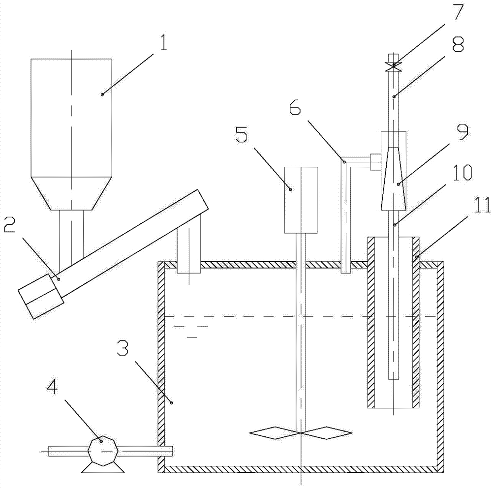
[0027] as attached figure 1 Shown, a kind of activated carbon dosing device, it packs the charcoal slurry tank 3 with exhaust pipe 6, jet pump 8 and gas-liquid separator 11, and the suction port of jet pump is communicated with charcoal slurry tank 3 through exhaust tube 6, and the jet flow The pump outlet pipe 9 is inserted into the gas-liquid separator 11, and the gas-liquid separator 11 is fixed on the carbon slurry tank 3, and the bottom of the gas-liquid separator 11 is located below the liquid level in the carbon slurry tank 3, and the gas-liquid separator 11 The top is positioned on the carbon slurry tank 3 top covers.

[0028] The working process of this embodiment is:

[0029] When the liquid level in the carbon slurry tank 3 reaches a certain position and needs to be fed, the conveyor 3 and the water inlet valve 7 are opened at the same time, and the carbon powder is transported to the carbon slurry tank 3 after being metered by the silo 1 through the screw conveyor...

Embodiment 2

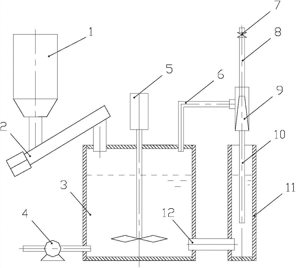
[0033] as attached figure 2 As shown, this embodiment is basically the same as Embodiment 1, the difference is that in this embodiment, the gas-liquid separator 11 is located outside the carbon slurry tank 3, and the gas-liquid separator 11 communicates with the carbon slurry tank 3 through a communication pipe 12 .

[0034] The working process of this embodiment is: when the liquid level in the carbon slurry tank 3 reaches a certain position and needs to be fed, the conveyor 3 and the water inlet valve 7 are opened at the same time, and the carbon powder is transported by the screw conveyor 3 after being measured by the silo 1 To the carbon slurry tank 3, the clean water enters the carbon slurry tank 3 through the water inlet valve 7 and the water inlet pipe 8 through the jet pump 9 and the gas-liquid separator 11 in turn. When the clean water flows through the jet pump 9, a jet suction is formed inside the jet pump 9 Function, the air containing suspended carbon powder par...

Embodiment 3

[0037] as attached figure 1 As shown in or 2, this embodiment is basically the same as Embodiment 1 or 2, the difference is that in this embodiment, the gas-liquid separator 11 has packing inside, which can play a role in stably discharging the airflow and further cleaning the air.


PUM


Abstract

The invention discloses an activated carbon feeding device and activated carbon feeding method. The activated carbon feeding device comprises a slurry tank, a jet pump and a gas-liquid separator; a hopper is arranged outside the slurry tank and communicated with the interior of the slurry tank; the air suction opening of the jet pump is communicated with the top of the carbon slurry tank by use of a suction pipe; a water outlet pipe of the jet pump is inserted into the gas-liquid separator, and the water outlet pipe extends into the lower part of the gas-liquid separator; the gas-liquid separator is fixedly arranged on the carbon slurry tank; the bottom of the gas-liquid separator is located under the liquid level in the carbon slurry tank, while the top of the gas-liquid separator is located above the top cover of the carbon slurry tank and communicated with the atmosphere.

Description

technical field [0001] The invention relates to an activated carbon dosing device, in particular to an activated carbon dosing device for powdered activated carbon. Background technique [0002] In order to improve the taste of water quality, at present, my country's tap water has successively adopted activated carbon adsorption technology to remove seasonal musty and other odors and odors, as well as to remove organic matter, surfactants, micro-pollutants in pesticides, algae, and industrial heavy metal pollution in water. Wait. There are two main ways to treat tap water with activated carbon adsorption process. One is that tap water passes through the granular activated carbon adsorption pool. The disadvantage of this method is that the adsorption capacity of granular activated carbon decreases with time and needs to be replaced regularly; The corresponding amount of powdered activated carbon powder is continuously added to the activated carbon adsorption tank. The advanta...

Claims


Application Information

Patent Timeline
Patent Type & Authority Applications(China)
IPC IPC(8): B01F13/10B01F15/02B01F13/06C02F1/28
Inventor 闫云涛郝长伟常慧齐树陶
Owner SHANDONG UNIV
Why Eureka
Try Eureka