A kind of led lamp base dispensing machine

A technology of LED lamp head and glue dispenser, which is applied to devices and coatings that apply liquid to the surface. It can solve the problems of inaccurate glue dispensing and uneven distribution of glue quantity, and achieve stable and accurate rotation and improved dispensing effect. , The dispensing effect is easy to control

Active Publication Date: 2018-11-13
佛山市顺德区格律诗自动化科技有限公司
View PDF8 Cites 1 Cited by
  • Summary
  • Abstract
  • Description
  • Claims
  • Application Information

AI Technical Summary

Problems solved by technology

[0006] In view of the existing automatic dispensing machines in the prior art, the LED lamp head is relatively static and the glue filling needle rotates to dispensing glue, which may easily lead to problems such as inaccurate dispensing and uneven distribution of glue amount. The present invention provides an LED lamp head point Glue machine, to better realize the dispensing of LED lamp holders, and improve the production efficiency of LED lamp automation

Method used


Image

  • A kind of led lamp base dispensing machine
  • A kind of led lamp base dispensing machine
  • A kind of led lamp base dispensing machine

Examples


Embodiment 1

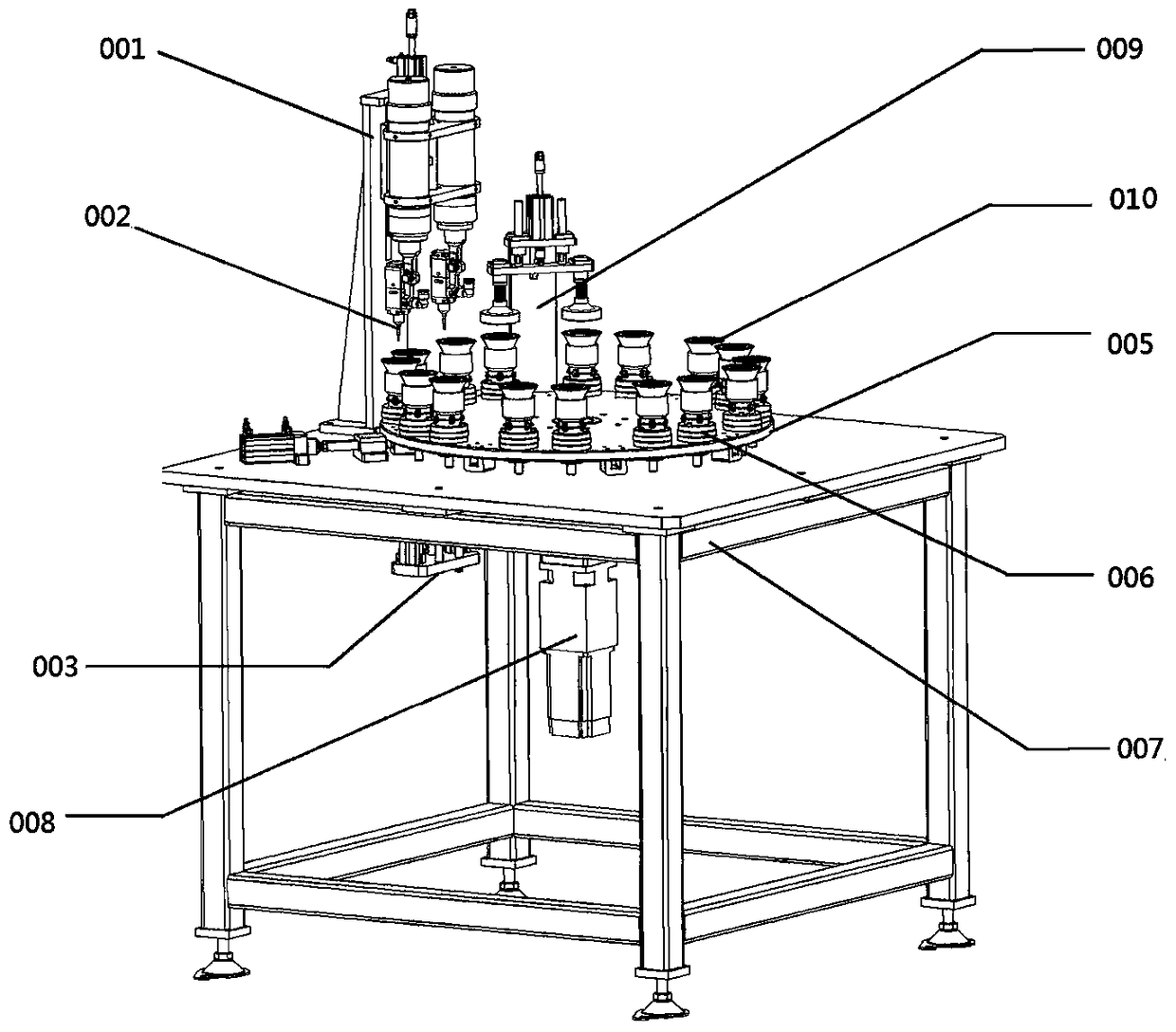
[0033] figure 1 It is a schematic diagram of the structure of the LED lamp holder dispensing machine in this embodiment, consisting of dispensing assembly 001, dispensing needle 002, dispensing frame 007, rotating drive assembly 003, base mounting plate 005, lamp base positioning seat 006, mounting plate motor 008 The base mounting plate 005 is rotatably mounted on the dispensing frame 007, the mounting plate motor 008 is mounted on the dispensing frame 007 and can drive the base mounting plate 005 to rotate, and the lamp head positioning seat 006 is rotatably mounted on the base mounting plate 005 Above, the rotation drive assembly 003 can drive the lamp head positioning seat 006 to rotate. In this embodiment, the rotary drive assembly 003 is preferably used to drive the lamp head positioning seat 006 to rotate through magnetic components.

[0034] Such as Figure 5 As shown, more specifically, the dispensing assembly 001 is composed of a second lifting cylinder 16, a rubbe...

Embodiment 2

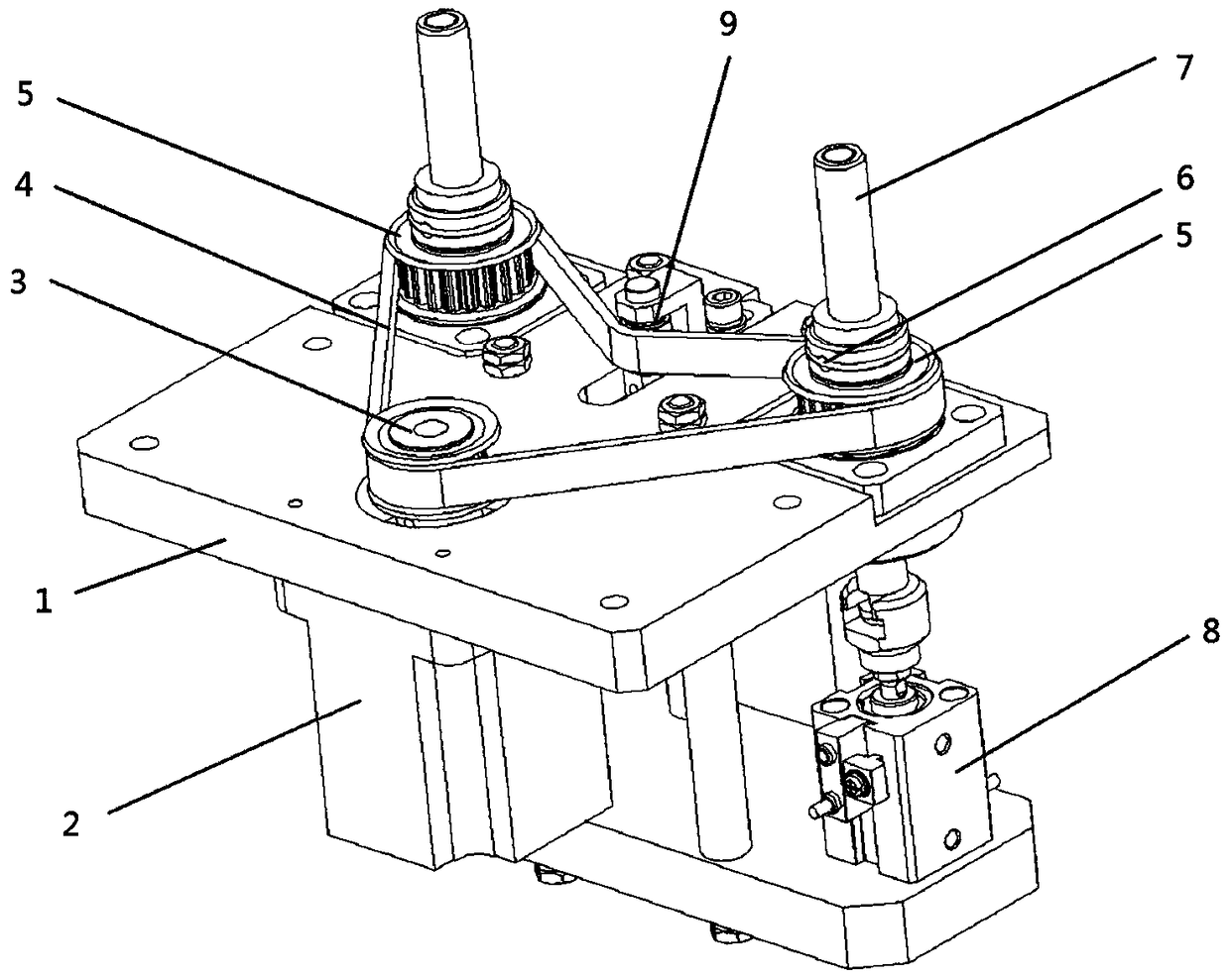
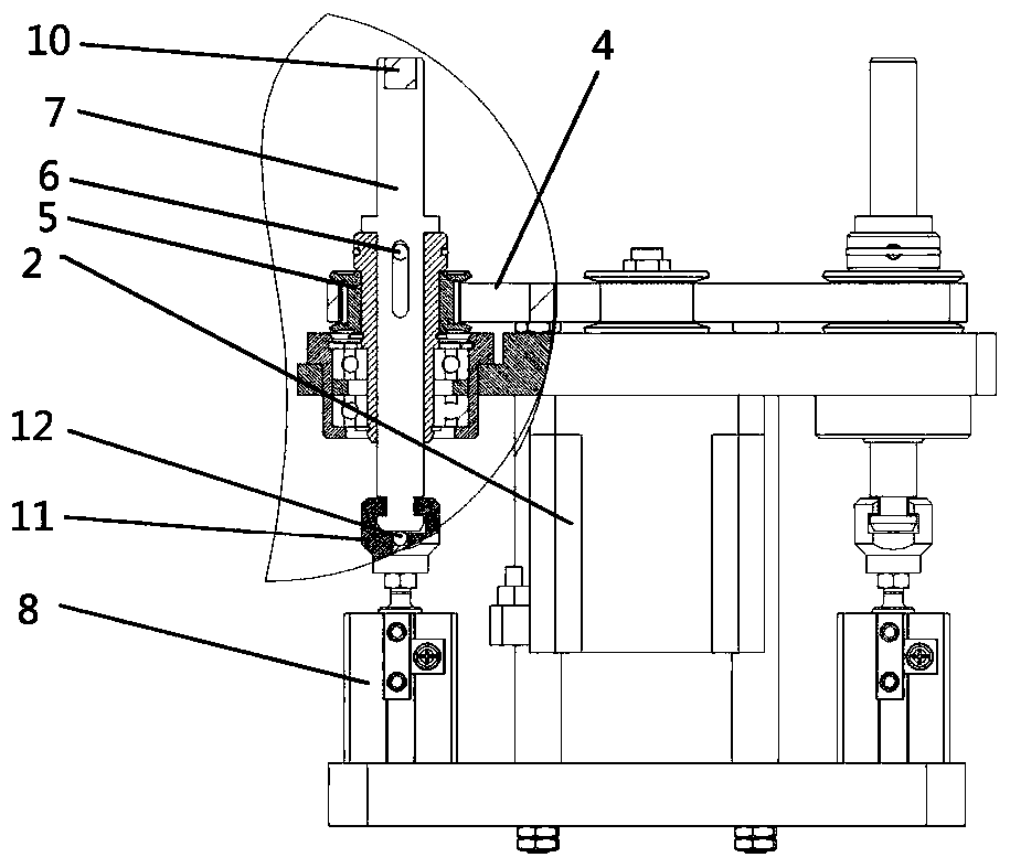
[0038] As a further step in Example 1, such as figure 2 , 3 , 4, the structure of the rotary drive assembly 003 consists of a mounting bracket 1, a driving motor 2, a driving pulley 3, a transmission belt 4, a driven pulley 5, a limit pin 6, a transmission connecting rod 7, a lifting cylinder 8, and a tensioner 9, magnetic block 10, connecting claw 11, rod sleeve 14, rod sleeve bearing 15 are formed.

[0039] The driving motor 2 and the lifting cylinder 8 are installed on the mounting bracket 1, the driving pulley 3, the driven pulley 5, and the tensioning pulley 9 are connected through the transmission belt 4, and the driving motor 2 drives the driving pulley 3 to rotate and then drives the driven pulley 5 rotation, the drive motor 2 and the driving pulley 3, the transmission belt 4, the driven pulley 5, and the tensioner 9 are designed to realize the function of driving the transmission connecting rod 7 to rotate. Other similar transmission structures are not mentioned one...


PUM


Abstract

The invention relates to the technical field of automatic LED lamp production equipment and in particular relates to an LED lamp cap dispenser. The LED lamp cap dispenser comprises a dispensing assembly, a dispensing needle, a dispensing rack, a rotary driving assembly, a base mounting disc, a lamp cap positioning seat and a mounting disc motor, wherein the base mounting disc is rotationally arranged on the dispensing rack; the mounting disc motor is arranged on the dispensing rack and can drive the base mounting disc to rotate; the lamp cap positioning seat is rotationally arranged on the base mounting disc; and the rotary driving assembly can drive the lamp cap positioning seat to rotate. According to the LED lamp cap dispenser disclosed by the invention, the lamp cap positioning seat is driven to rotate, rotation of the LED lamp cap on the automatic production line is realized, the dispensing needle is stationary in the dispensing process, stable dispensing in the operation of the dispensing assembly is promoted, the problem that the dispensing needle is vibrated and collided is solved, and the dispensing effect is easy to control.

Description

technical field [0001] This patent relates to the technical field of automatic LED lamp production equipment, in particular to an LED lamp cap dispensing machine. Background technique [0002] Light-emitting diode lamps, commonly known as LED lamps, refer to appliances that can transmit light, distribute and change the light distribution of LED light sources, including all parts and components required to fix and protect LED light sources except for LED light sources, as well as everything connected to the power supply. Required line accessories. With its technical characteristics of high efficiency, energy saving, long life, and small size, LED lamps are becoming the main product in the new generation lighting market, and they are powerfully driving the rapid development of the environmental protection and energy saving industry. Under the background of rising global energy shortage concerns, saving energy is an important issue we will face in the future. In the field of l...

Claims


Application Information

Patent Timeline
Patent Type & Authority Patents(China)
IPC IPC(8): B05C5/02B05C11/10
CPCB05C5/0208B05C5/0225B05C13/02
Inventor 倪明金水明
Owner 佛山市顺德区格律诗自动化科技有限公司
Why Eureka
Try Eureka