

Reamer
A technology of reaming machine and frame, which is applied in the field of reaming machines, can solve the problems of low production efficiency, metal pipe damage, high temperature and other problems in the production line, and achieve the effect of improving production efficiency
- Summary
- Abstract
- Description
- Claims
- Application Information
AI Technical Summary
Problems solved by technology
Method used
Image

Examples
Embodiment 1
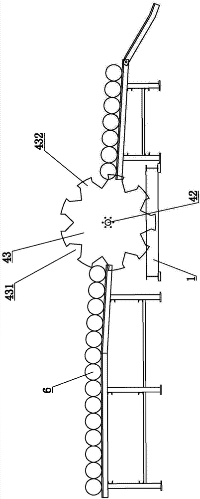
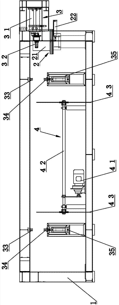
[0054] figure 1 It is a structural schematic diagram of Embodiment 1 of the hole reaming machine of the present invention; figure 2 It is another structural schematic diagram of Embodiment 1 of the hole reaming machine of the present invention.
[0055] refer to figure 1 and figure 2 , a hole reaming machine, comprising a frame 1, on which an electromagnetic heating device 2 and a hole reaming device 3 are sequentially arranged from front to back; the electromagnetic heating device 2 includes an electromagnetic heating coil 21, and the hole reaming device 3 includes a first power unit 31 drives the reaming head 32. In the present embodiment, the first power unit 31 adopts a hydraulic cylinder. Rotating shaft 42, rotating shaft 42 is arranged on the frame 1 through the lateral rotation of the bearing, the second power device 41 adopts a motor, and the motor and the rotating shaft 42 are connected by a sprocket chain transmission, and the two ends of the rotating shaft 42 a...
Embodiment 2
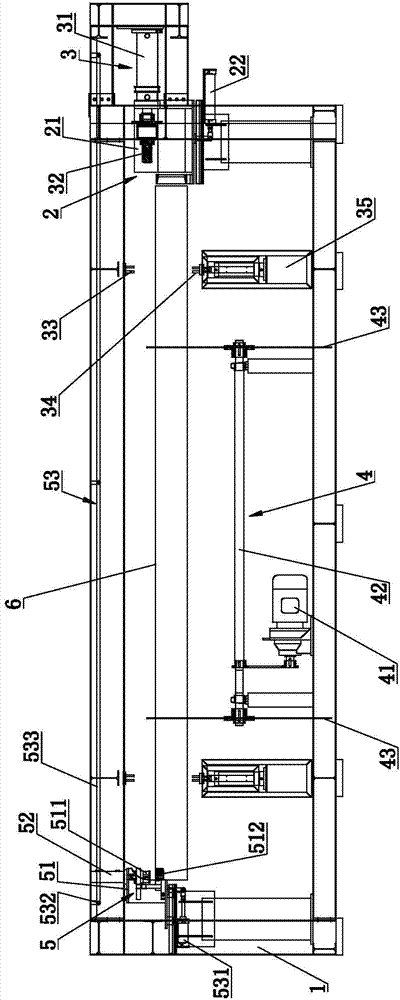
[0061] image 3 It is a structural schematic diagram of the second embodiment of the hole reaming machine of the present invention; Figure 4 It is a top view structure schematic diagram of the second embodiment of the hole reaming machine of the present invention; Figure 5 It is a structural schematic diagram of the process hole punching linkage device in the second embodiment of the hole reaming machine of the present invention; Figure 6 yes Figure 5 Schematic diagram of the punch holder in .
[0062] refer to image 3 , Figure 4 , Figure 5 as well as Figure 6 , the structure of this embodiment is basically the same as that of Embodiment 1, and the difference is that: for the reaming machine of this embodiment, the two ends of the frame 1 are respectively provided with a process hole punching device 5, and the process hole punching device 5 includes punching The head frame 51, the top of the punch frame 51 is fixedly provided with a punch 511 driven by the fourt...
Embodiment 3
[0069] Figure 7 It is a structural schematic diagram of the punch in the third embodiment of the hole reaming machine of the present invention; Figure 8 yes Figure 7 A schematic diagram of the three-dimensional structure.
[0070] refer to Figure 7 and Figure 8 , the structure of this embodiment is basically the same as that of Embodiment 2, the difference is that the punch 511 includes a punch body 5111, an elastic rod 5112 covering the periphery of the punch body 5111, and the elastic rod 5112 is provided with a punch 511 The diameter of the through hole on the elastic rod 5112 is smaller than the diameter of the punch body 5111, and the punch body 5111 and the through hole have an interference fit; the head of the punch body 5111 retracts into the elastic rod 5112.
[0071] In this embodiment, the elastic rod 5112 is a polyester rod, and the lower end of the polyester rod is covered with a metal sheath 5113. The metal sheath 5113 includes a bottom guard plate, and ...
PUM
 Abstract
Description
Claims
Application Information