Cold-forging technology for safety belt transmission shaft and die structure of molded transmission patterned tooth

A technology for transmission shafts and safety belts, which is applied in the manufacture of tools, engine components, metal processing equipment, etc., can solve the problems of many processing procedures, waste of materials, and low processing efficiency, so as to reduce processing procedures, reduce production costs, and improve production efficiency effect

Active Publication Date: 2015-04-08
SUZHOU INDAL PARK XINKAI PRECISION FASTENERSCO
View PDF5 Cites 9 Cited by
  • Summary
  • Abstract
  • Description
  • Claims
  • Application Information

AI Technical Summary

Problems solved by technology

[0002] At present, in the auto parts manufacturing industry, the drive shaft of the seat belt is mainly realized in two ways in the manufacturing process of forming the transmission splines and special-shaped rib teeth. First, the drive splines and special-shaped rib teeth are milled by CNC. Second, Firstly, the special-shaped rib teeth are formed by die-casting, and then the transmission flower teeth are formed by rolling and rubbing. These two forming methods require different processing methods, and the internal streamlines of the metal are not complete and the strength is not high, so it is impossible to form more than two kinds of flower teeth at the same time. Tooth structure, many processing procedures, low processing efficiency, a lot of material wasted in the processing process, long production cycle, low mold life, does not meet the needs of enterprises to reduce costs

Method used


Image

  • Cold-forging technology for safety belt transmission shaft and die structure of molded transmission patterned tooth
  • Cold-forging technology for safety belt transmission shaft and die structure of molded transmission patterned tooth
  • Cold-forging technology for safety belt transmission shaft and die structure of molded transmission patterned tooth

Examples


Embodiment Construction

[0029] The present invention will be described in detail below in conjunction with the accompanying drawings.

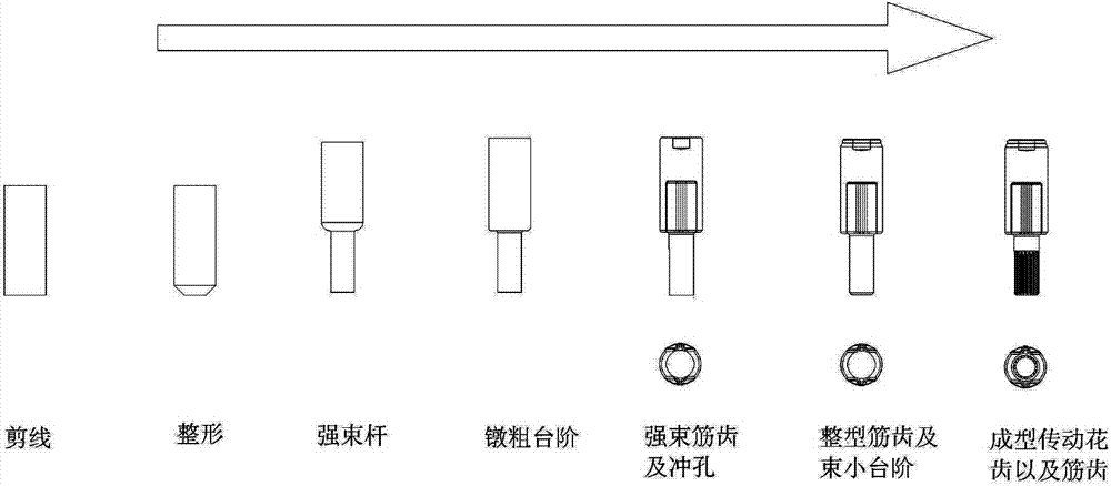
[0030] Such as figure 1 Shown is a cold heading process for a seat belt transmission shaft, the process steps are:

[0031] S1, cutting wire;

[0032] S2, shaping the wire rod;

[0033] S3, strong beam rod;

[0034] S4, upsetting steps;

[0035] S5, strong rib teeth and punching;

[0036] S6, Shaping tendon teeth and beam small steps;

[0037] S7. Forming transmission flower teeth and rib teeth.

[0038] The wire is work hardened.

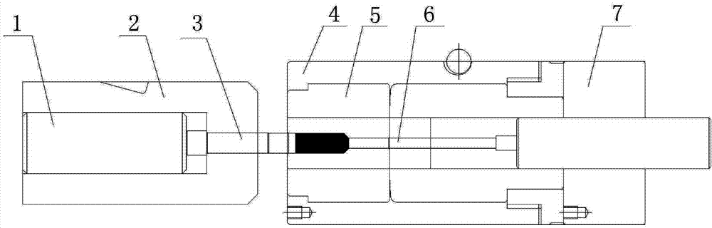
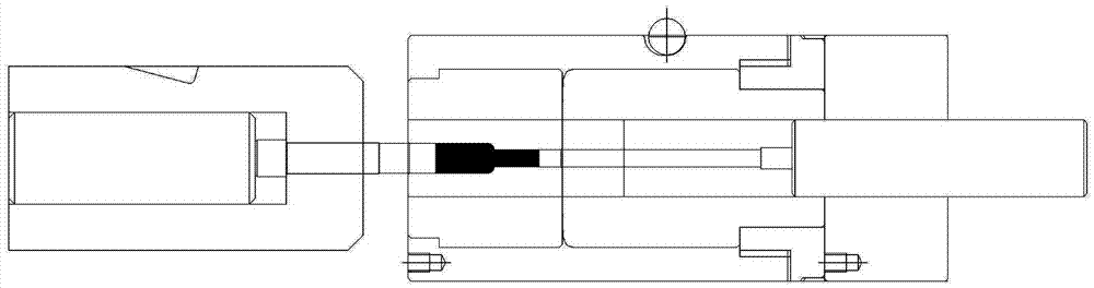
[0039] Such as Figure 7 A mold structure for forming transmission teeth in step S7 is shown, including a main mold unit and a die unit, the main mold unit includes a main mold sleeve 15, and a main mold back pad is provided at the bottom of the main mold sleeve 15 plate 22, the die unit includes a die set 8, a molding die 14 is arranged on the die set 8, and the upper part 16 of the main die, the middle part 17 of the main die a...


PUM


Abstract

The invention relates to a cold-forging technology for a safety belt transmission shaft and a die structure of a molded transmission patterned tooth. The process comprises the following steps: S1, trimming a wire rod; S2, shaping; S3, intensifying a rod part; S4, upsetting a step; A5, intensifying a tenon tooth and punching; S6, shaping the tenon tooth and intensifying a small step; S7, molding the transmission patterned tooth. The die structure comprises a master die unit and a punching unit, wherein the master die unit comprises a master die cover and a master die back base plate; the punching unit comprises a punching cover and a moulding cover, wherein the master die cover is internally provided with a master die upper section, a master die middle section and a master die lower section, and a master die ejector pin is arranged in the middle of the master die cover; the punching cover is internally provided with an upper punching die cushion block, a middle punching die cushion block and a lower punching die cushion block, a punching pin is arranged in the middle of the punching cover, a blind hold is formed in the middle of the middle punching die cushion block, a small cushion block is arranged in the blind hold, and a spring is arranged at the bottom of the small cushion block. All sizes of the products are accomplished by virtue of the cold-forging technology and the molded product is complete in streamline and high in strength of spare parts, so that the production efficiency of the product can be improved.

Description

technical field [0001] The invention relates to the manufacturing industry of auto parts, in particular to a cold heading process for a safety belt transmission shaft used for an automobile seat and a mold structure for forming transmission teeth. Background technique [0002] At present, in the auto parts manufacturing industry, the drive shaft of the seat belt is formed in the manufacturing process of the transmission splines and special-shaped rib teeth mainly through two methods. First, the drive splines and special-shaped rib teeth are milled by CNC. Second, , first die-casting shaped rib teeth, and then rolling and rolling to form transmission flower teeth. These two forming methods require different processing methods, and the internal flow line of the metal is not complete and the strength is not high, so it is impossible to form more than two kinds of flower teeth at the same time. Tooth structure, many processing procedures, low processing efficiency, a large amoun...

Claims


Application Information

Patent Timeline
Patent Type & Authority Applications(China)
IPC IPC(8): B21K1/12B21J13/02B21J5/02
CPCB21J5/02B21J13/02B21K1/12
Inventor 王宁田小娟
Owner SUZHOU INDAL PARK XINKAI PRECISION FASTENERSCO
Why Eureka
Try Eureka