
Air floatation conveyer

A technology of air flotation and air intake holes, which is applied in the direction of transportation and packaging, conveyors, non-mechanical conveyors, etc., can solve the problems of small driving capacity, workpiece disturbance, etc., achieve easy layout, large motion acceleration, and reduce static pollution And the effect

Active Publication Date: 2015-04-08
阿尔贝斯(长兴)科技有限公司
View PDF14 Cites 18 Cited by
  • Summary
  • Abstract
  • Description
  • Claims
  • Application Information

AI Technical Summary

Problems solved by technology

[0010] Purpose of the invention: In order to overcome the deficiencies in the prior art, the present invention provides an air flotation transportation device, which can realize complete non-contact transportation, and solve the problem that the existing air flotation transportation device has a small driving ability and is easy to damage the workpiece. Disturbance problems, but also can reduce electrostatic pollution and stress concentration on the surface of the workpiece

Method used


Image

  • Air floatation conveyer
  • Air floatation conveyer
  • Air floatation conveyer

Examples


Embodiment Construction

[0030] The present invention will be further described below in conjunction with the accompanying drawings.

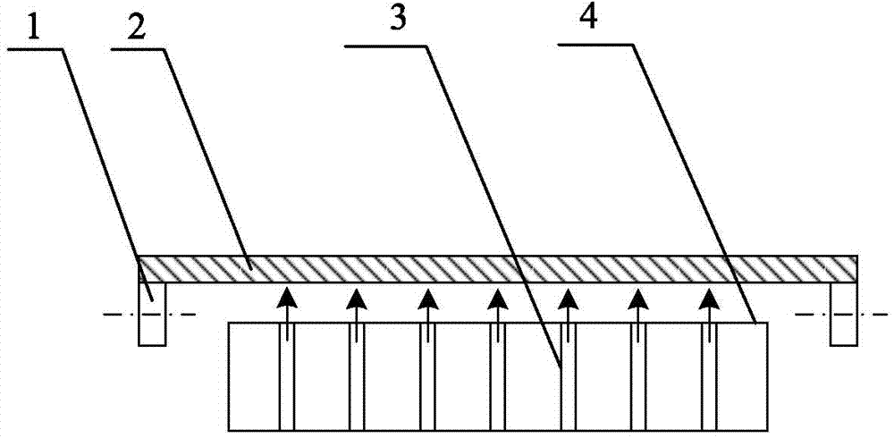
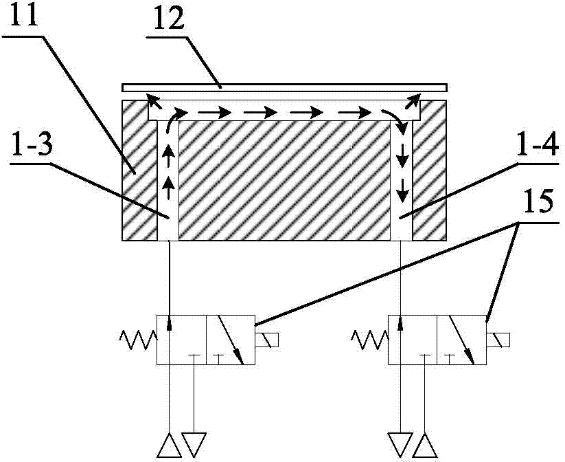
[0031] like Figure 3 to Figure 11 As shown, an air flotation transport device includes a flat plate 11 with a smooth surface, the surface of the flat plate 11 is provided with a plurality of grooves 1-2 distributed symmetrically, and the grooves 1-2 are separated from each other by the surface of the flat plate 11, And the number of grooves 1-2 is greater than 4. The grooves 1-2 on the surface of the flat plate 11 may be circular, square or cross-shaped, and the depth of the grooves 1-2 is greater than 200 microns and less than 500 microns. Air inlet holes 1-3 and air outlet holes 1-4 are formed in pairs inside the groove 1-2, and threads are formed on the bottom surface of the flat plate 11 where the air inlet holes 1-3 and the air outlet holes 1-4 are located for connecting Air supply connection. Inlet holes 1-3 supply positive pressure, and outlet holes 1-4 supp...


PUM


Abstract

The invention discloses an air floatation conveyer comprising a flat plate which is provided with a plurality of symmetrically distributed recesses. Each recess is internally and pairwise provided with air inlets and air outlets both in the vertical direction; the air inlets and the air outlets are connected with compressed air incoming pipes and compressed air outgoing pipes, respectively; each compressed air incoming pipe and each compressed air outgoing pipe are communicated with positive and negative pressure sides of an air source through electromagnetic reversing valves, respectively. The air horizontally flows in the recesses, a workpiece can be driven to move by making greatest use of vicious force of the air flow, a high motion acceleration is acquired, the problem that the existing air flotation conveyer has low driving capacity and easily causes interference to the workpiece is solved, and electrostatic pollution and workpiece surface stress concentration can be lessened.

Description

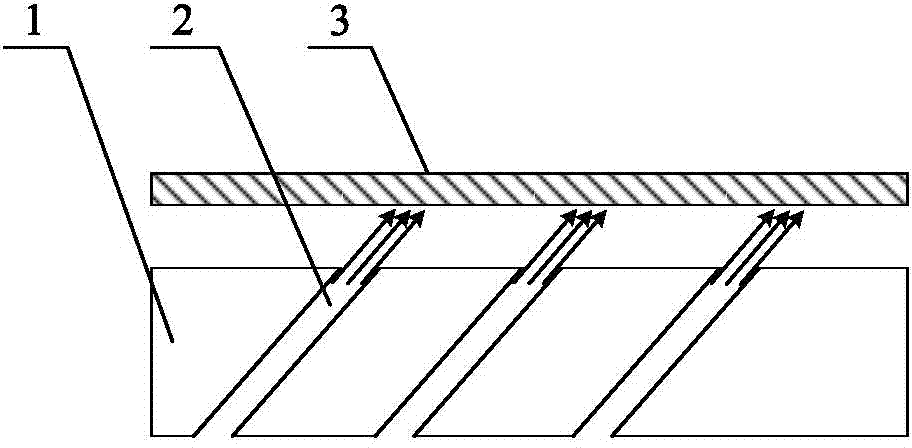
technical field [0001] The invention relates to an air flotation transportation device, and relates to the technical field of non-contact transportation in the manufacturing of semiconductor wafers and glass substrates. Background technique [0002] Liquid crystal glass substrates and semiconductor wafers must be transported on the production line in a safe and nondestructive manner during the production process. At present, non-contact transportation is generally used to transport such workpieces. The usual method is to form a layer of air film between the workpiece and the surface of the transport device, so as to suspend the workpiece above the device, so as to prevent the workpiece from being transported during the transmission process. Contact with the surface of the device can cause damage. Among the existing suspension transmission equipment, the more typical ones are Chinese patent application "A kind of air suspension device" (application publication number CN20196...

Claims


Application Information

Patent Timeline
Patent Type & Authority Applications(China)
IPC IPC(8): B65G54/00
CPCB65G54/00
Inventor 钟伟
Owner 阿尔贝斯(长兴)科技有限公司
Learn More