
A new type of high pressure chemical gear pump

A gear pump, chemical technology, used in pumps, pump components, rotary piston pumps, etc., can solve the problem of unstable liquid flow, unreachable pressure, use accuracy, metering level, circulation efficiency, transmission performance, and difficult installation and maintenance. Satisfaction and other problems, to achieve the effect of smooth pumping operation and extended service life

Active Publication Date: 2017-05-03
何祥军
View PDF5 Cites 0 Cited by
  • Summary
  • Abstract
  • Description
  • Claims
  • Application Information

AI Technical Summary

Problems solved by technology

[0002] Most of the current gear pumps use a pair of spur-toothed gears to mesh with each other to deliver liquid, so that the delivery pressure difference of the pump will not be very high, and the lateral force of the gears may be generated. Generally, the maximum pressure difference can reach 15.5bar and the outlet pressure can A gear pump that reaches about 21bar is quite good. For example, under the conditions of high outlet pressure (34.5bar), high pressure difference (24.1bar) and high temperature (260°C), it is difficult to ensure the effective long-term operation of the pump. , or basically cannot be effectively transported, the pressure cannot be reached at all, the life is extremely short, and it is easily damaged, which cannot meet the needs of current production
[0003] Most of the traditional gear pumps are gear oil pumps, which barely deliver low-pressure and low-temperature (such as about 70°C) oils with self-lubricating liquids. It is difficult to transport normally. Due to the simplicity and insufficiency of the current design and processing, and the inability to select the appropriate combination of metal and non-metal materials, it is dangerous for toxic, harmful, volatile, easy to corrode, easy to crystallize, and various harsh chemical media. , basically cannot be transported correctly and effectively, so that the scope of use is very limited. Its use accuracy, measurement level, cycle efficiency, transmission performance, installation and maintenance are difficult to meet the requirements of current production and life. The wear of pumps and gears is very severe, and maintenance is difficult. Large, high cost of use, low efficiency of the pump, so the service life of the pump is very short
[0004] Most of the traditional gear pumps use simple mechanical couplings to connect the pump and the motor through the long shaft coupling, and convert the mechanical energy output by the motor into hydraulic energy through the gears, but this simple connection will cause the pump and the motor to be disconnected. The centering of the shaft cannot be guaranteed, which leads to unbalanced pressure on the pump shaft and the mechanical seal, resulting in a large radial load, which limits the increase in its pressure, and easily leads to leakage, unstable liquid flow, and large pulsation , the noise is particularly loud, causing the interface or pipeline to vibrate, the equipment is easily damaged, and directly affects the normal service life of the pump, especially the toxic, harmful, volatile, easy to corrode, easy to crystallize, and dangerous medium, which will cause damage to the environment. Destruction, waste of resources, and more serious injuries to personnel, so they cannot be used widely and effectively

Method used


Image

  • A new type of high pressure chemical gear pump
  • A new type of high pressure chemical gear pump
  • A new type of high pressure chemical gear pump

Examples


Embodiment Construction

[0034] The following will further describe the technical solutions of the embodiments of the present invention in conjunction with the accompanying drawings in the embodiments of the present invention. Obviously, the described embodiments are only some of the embodiments of the present invention, not all of them. Based on this The embodiment of the invention, and all other embodiments obtained by those skilled in the art without making special breakthroughs and creative work, but simply replacing or replacing, all fall within the protection scope of the present invention.

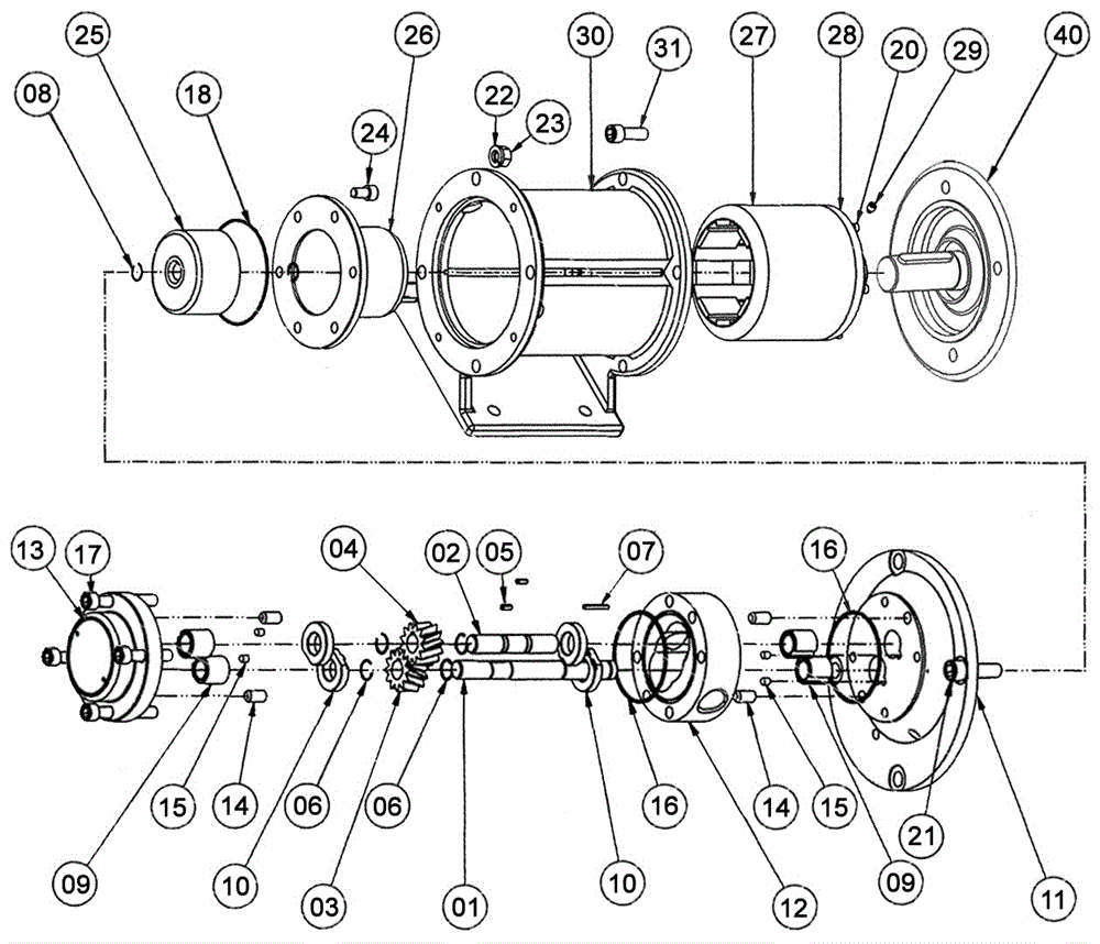
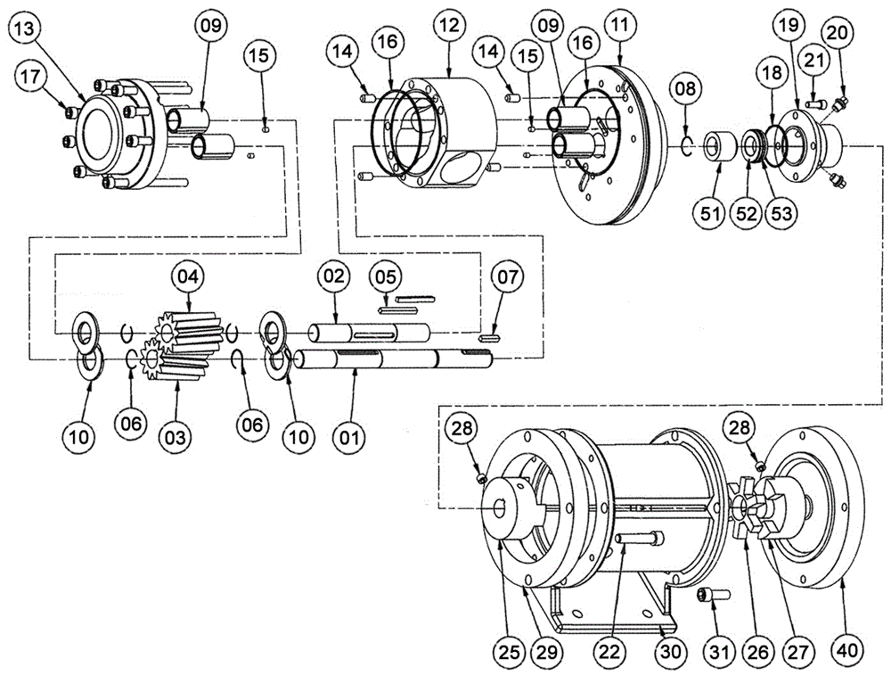
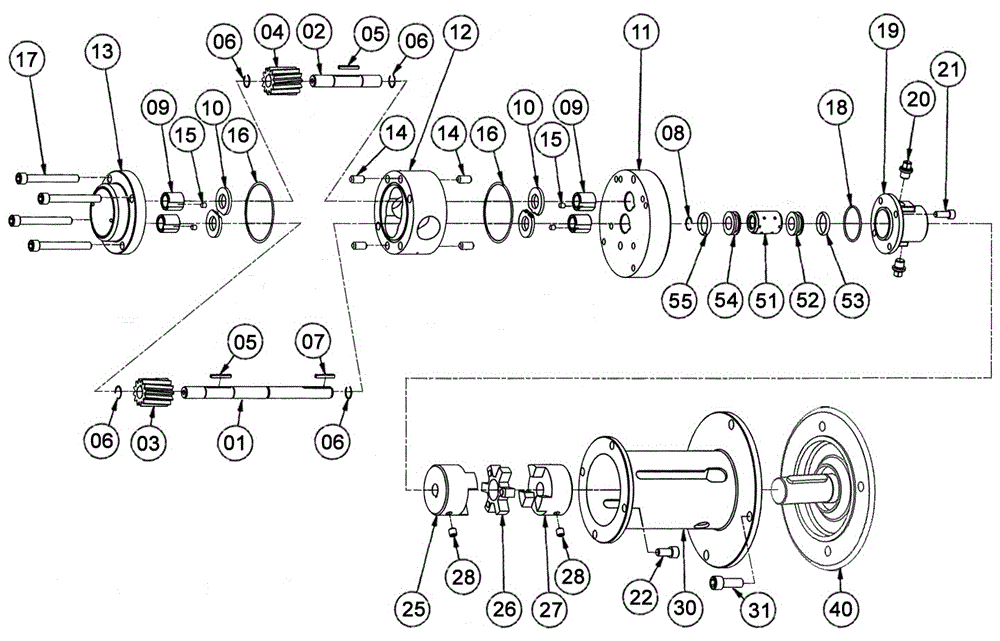
[0035] The embodiment of the present invention relates to a novel high-pressure chemical gear pump, figure 1 The design adopts a pair of unique helical gears capable of high-pressure pumping and wear-resistant plates with pressure relief grooves, which can make the delivery pressure up to (34.5bar) and high pressure difference (24.1bar), flow rate up to 75L / M and high temperature (260 °C) working conditions...


PUM


Abstract

The invention relates to a pump and particularly relates to a novel high-pressure chemical industry gear pump which is used for conveying various chemical media, corrosive and dangerous chemicals, or oil or water or toxic and harmful liquids or inflammable and detonable liquids and has high pressure resistance, high temperature resistance, corrosion resistance, acid and alkali resistance and abrasion resistance. According to the novel high-pressure chemical industry gear pump, a pair of unique helical gears capable of resisting high-pressure pumping and a wear-resisting plate with a pressure relief groove are designed and adopted; by virtue of innovatively designing the structure, improving the processing process, reasonably selecting metal and nonmetal combined materials, and adopting short-axis coupling and magnetic driving mode of a self-alignment structure or a mechanical seal mode of a coupling with an elastomer to connect driving between the pump and a motor, working conditions with high pressure, high pressure difference and various viscosity are met, various harsh chemical media are efficiently delivered, the defect or blank of the prior is overcome, zero leakage and no pulse are really realized, the leakage problem of an existing shaft seal is solved, and extensive application in various industries such as petroleum and chemical industry is met.

Description

technical field [0001] The present invention relates to the technical field of pumps, in particular to a method for transporting various chemical media, corrosive and dangerous chemicals, or oil or water or poisonous or harmful or flammable and explosive liquids, with a pressure difference up to 24.1bar and the highest outlet A new type of high-pressure chemical gear pump with a pressure of 34.5bar, high temperature resistance, corrosion resistance, acid and alkali resistance, and wear resistance. Background technique [0002] Most of the current gear pumps use a pair of spur-toothed gears to mesh with each other to deliver liquid, so that the delivery pressure difference of the pump will not be very high, and the lateral force of the gears may be generated. Generally, the maximum pressure difference can reach 15.5bar and the outlet pressure can A gear pump that reaches about 21bar is quite good. For example, under the conditions of high outlet pressure (34.5bar), high press...

Claims


Application Information

Patent Timeline
Patent Type & Authority Patents(China)
IPC IPC(8): F04C2/16F04C11/00F04C15/00
CPCF04C2/16F04C15/0003F04C2240/40F04C2240/801
Inventor 何祥军
Owner 何祥军
Learn More