Boom anti-collision device, boom anti-collision method and engineering machinery

A collision device and boom technology, which is applied to measuring devices, force/torque/work measuring instruments, instruments, etc., can solve the problems of complex algorithms, unrecognizable, dependence on effectiveness, etc., to achieve simple and reliable algorithms, improve safety, Detecting effects with high accuracy

Active Publication Date: 2015-04-08
HUNAN SANY INTELLIGENT CONTROL EQUIP
View PDF8 Cites 1 Cited by
  • Summary
  • Abstract
  • Description
  • Claims
  • Application Information

AI Technical Summary

Problems solved by technology

However, the infrared or laser ranging method is easily affected by the external environment such as occlusion, and this method is directional, so it cannot realize the full coverage detection of the boom, and the application effect has great limitations.
However, the angle sensor and speed sensor are used to plan the attitude and motion trajectory of the boom. Due to the complexity of the algorithm, high requirements are placed on the computing power of the controller, and it is heavily dependent on the validity of the motion model established by the user. The cost is high, and a strict debugging and calibration process is required before application. The promotion of this technology has a certain threshold
[0003] The patent application number is CN201110025905, which proposes a method of boom collision detection using a noise sensor. This method has a better effect than infrared or laser detection, but this method can only determine the location of the impact, and cannot detect the size and magnitude of the impact force. direction, and the detection of impact noise needs to filter out the environmental noise, the effect depends on the effectiveness of the filtering algorithm, and when there is a similar impact sound in the environmental noise, it will not be possible to identify whether it is the impact of the jib

Method used


Image

  • Boom anti-collision device, boom anti-collision method and engineering machinery
  • Boom anti-collision device, boom anti-collision method and engineering machinery
  • Boom anti-collision device, boom anti-collision method and engineering machinery

Examples


Embodiment Construction

[0022] In order to enable those skilled in the art to better understand the technical solutions of the present invention, the present invention will be further described in detail below in conjunction with the accompanying drawings.

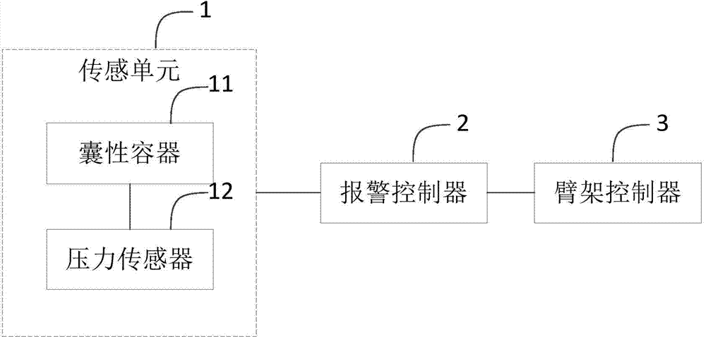
[0023] see figure 1 , figure 1 It is a functional block diagram of a boom anti-collision device provided by an embodiment of the present invention.

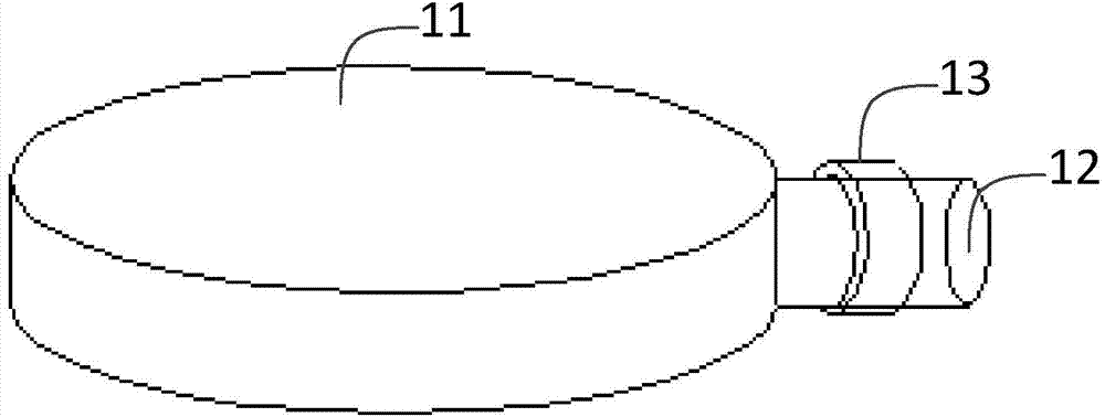
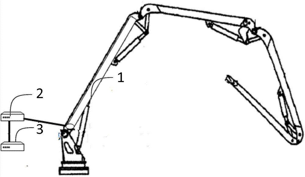
[0024] The invention provides a boom anti-collision device, comprising: a sensing unit 1, at least including a capsule container 11 filled with gas or liquid and a pressure sensor 12 connected to the end of the capsule container 11 to form a closed space, the The sensing unit 1 is arranged along the surface of the arm frame of the mechanical device for detecting the impact force generated by the collision between the arm frame and the obstacle, and sends out a pressure signal; the alarm controller 2 is connected with the sensing unit 1 for transmitting the pressure The signal is compared with the ...


PUM


Abstract

The invention discloses a boom anti-collision device comprising a sensing unit and an alarm controller. The sensing unit at least comprises a sac-like container filled with gas or liquid and a pressure sensor connected with the tail end of the sac-like container to form a closed space. The sensing unit is arranged along the surface of a boom of a mechanical device and used for detecting the impact force generated by collision between the boom and an obstacle and sending out a pressure signal. The alarm controller is connected with the sensing unit and used for comparing the pressure signal with a preset pressure range, and giving an alarm and sending alarm information to a boom controller of the mechanical device if the detected pressure is greater than the preset pressure range. With the device, whether the boom suffers from collision and the size of the impact force on the boom can be detected. The invention further discloses a piece of engineering machinery comprising the boom anti-collision device and a boom anti-collision method.

Description

technical field [0001] The invention relates to the field of construction machinery, in particular to an anti-collision device and method for a boom and construction machinery. Background technique [0002] Many large-scale construction machinery, especially construction machinery with multi-section boom or bending structure, such as concrete pump trucks, cranes, excavators, etc., need to control the boom, but it is easy to encounter surrounding obstacles during operation material, causing a safety accident. At present, most of the collision detection technologies of booms use infrared or laser ranging, or use angle sensors and speed sensors to plan boom attitude and motion trajectory. However, the infrared or laser ranging method is easily affected by the external environment such as occlusion, and this method is directional, so it cannot realize the full coverage detection of the boom, and the application effect has great limitations. However, the angle sensor and speed ...

Claims


Application Information

Patent Timeline
IPC IPC(8): G01L5/00
Inventor 何银菊张钰旻裴芳
Owner HUNAN SANY INTELLIGENT CONTROL EQUIP
Why Eureka
Try Eureka