Method for measuring static d-axis and q-axis inductance and rotary transformer zero position of permanent magnet synchronous motor

A technology of permanent magnet synchronous motor and AC-D axis inductance, which is applied in the control of generators, motor control, motor generator control, etc. It can solve the problem of unsatisfactory resolution zero position accuracy, complex and time-consuming process, and inability to obtain the resolution zero position. and other problems, to achieve the effect of simple and reliable algorithm and operation, low cost, and no personal safety risk

Inactive Publication Date: 2018-02-16
HEFEI JUYI POWER SYST CO LTD
View PDF1 Cites 3 Cited by
  • Summary
  • Abstract
  • Description
  • Claims
  • Application Information

AI Technical Summary

Problems solved by technology

[0003] The existing static AC-D axis inductance is obtained through electromagnetic simulation. The motor simulation tends to be more ideal, and the actual situation may be different. To obtain the zero position of the resolver through bench calibration, the motor and the motor controller need to be installed on the test bench. Frame, and then the experimenter operates the gantry and related software to obtain it. The process is complicated and time-consuming, and it cannot satisfy the situation of obtaining the zero position of the resolver without the need for gantry calibration.
The accuracy of the zero position of the resolver obtained by self-learning is not ideal, and it needs the support of the motor controller

Method used


Image

  • Method for measuring static d-axis and q-axis inductance and rotary transformer zero position of permanent magnet synchronous motor
  • Method for measuring static d-axis and q-axis inductance and rotary transformer zero position of permanent magnet synchronous motor
  • Method for measuring static d-axis and q-axis inductance and rotary transformer zero position of permanent magnet synchronous motor

Examples


Embodiment Construction

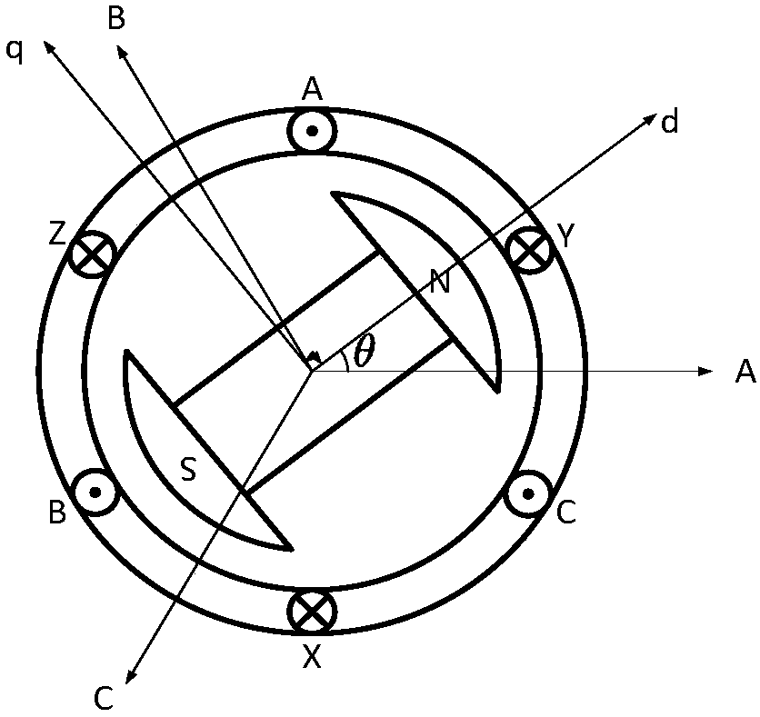
[0047] Such as figure 1 As shown, it is the physical model of the permanent magnet synchronous motor, and the inductance matrix in the A, B, C three-phase static coordinate system is:

[0048]

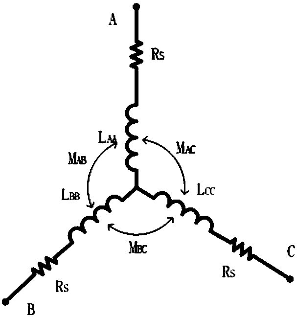
[0049] where L AA , L BB , L CC Respectively A, B, C three-phase self-inductance, M AB , M BA , M BC , M CB , M AC , M CA For A, B, C three mutual inductance.

[0050] Since the three-phase stator windings have a mutual difference of 120° in space, the self-inductance of the A, B, and C three-phase stator windings is shown in the following formula.

[0051]

[0052] where L S0 is the average value of the self-inductance of the A-phase stator winding, L S2 It is the amplitude of the second harmonic of the self-inductance of the A-phase stator winding.

[0053] The mutual inductance of the A, B, and C three-phase stator windings is shown in the following formula.

[0054]

[0055] where M S0 is the absolute value of the average mutual inductance of the stator windi...


PUM


Abstract

The invention discloses a method for measuring the static d-axis and q-axis inductance and the rotary transformer zero position of a permanent magnet synchronous motor. The method includes the following steps: measuring the three-phase static inductance through the bridge, and getting the average value of self inductance of the phase-A stator winding, the amplitude of second harmonic and the current position angle of the rotor according to the relationship of the three-phase static inductance, the self inductance and the mutual inductance; calculating the d-axis inductance and the q-axis inductance according to the relationship of the three-phase inductance matrix, the self inductance and the mutual inductance; and acquiring the position angle of the rotary transformer, and subtracting thecurrent position angle of the rotor from the position angle of the rotary transformer to get the zero position angle of the rotary transformer. According to the scheme, the three-phase static inductance is measured through the bridge, the d-axis static inductance and the q-axis static inductance are obtained through conversion, and the algorithm and the operation are simple and reliable. The zeroposition of the rotary transformer can be calculated according to the position angle of the rotary transformer read by a principal computer and the current position angle of the rotor, without the need to consider the current position of the rotor and the calibration of a test bench. The static d-axis and q-axis inductance and the rotary transformer zero position can be obtained without support of a motor controller or high-voltage equipment. The cost is low, and there is no risk to the personal safety.

Description

technical field [0001] The invention relates to a permanent magnet synchronous motor, in particular to a method for measuring static AC-D axis inductance and resolver zero position of a permanent magnet synchronous motor. Background technique [0002] The permanent magnet synchronous motor has become the mainstream of the pure electric vehicle drive system. The measurement of the AC-D axis inductance and the zero position of the resolver will directly affect the performance and efficiency of the permanent magnet synchronous motor. The existing measurement of the inductance of the orthogonal and direct axis is mainly obtained through electromagnetic simulation, and the measurement of the zero position of the resolver is basically obtained through bench calibration or self-learning. [0003] The existing static AC-D axis inductance is obtained through electromagnetic simulation. The motor simulation tends to be more ideal, and the actual situation may be different. To obtain t...

Claims


Application Information

Patent Timeline
Patent Type & Authority Applications(China)
IPC IPC(8): H02P21/16H02P21/18
CPCH02P2207/05H02P21/16H02P21/18
Inventor 刘蕾方质彬范佳伦班建安张茨
Owner HEFEI JUYI POWER SYST CO LTD
Why Eureka
Try Eureka