
Light path system of trace gas sensor and air chamber

A trace gas, optical path system technology, applied in instruments, measuring devices, scientific instruments, etc., can solve problems such as difficult to meet the requirements of online testing, unrealistic, and achieve the effect of compact structure, reduced volume, and accurate detection

Inactive Publication Date: 2015-04-08
GL TECH CO LTD
View PDF5 Cites 5 Cited by
  • Summary
  • Abstract
  • Description
  • Claims
  • Application Information

AI Technical Summary

Problems solved by technology

Due to the limitations of the on-site environment and detection equipment, it is unrealistic to use the usual through-beam optical path, and it is difficult to meet the requirements of on-line testing. Therefore, an optical path system that satisfies a longer optical path and has a smaller volume is required.

Method used


Image

  • Light path system of trace gas sensor and air chamber
  • Light path system of trace gas sensor and air chamber
  • Light path system of trace gas sensor and air chamber

Examples


Embodiment 1

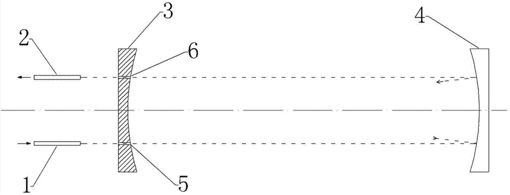
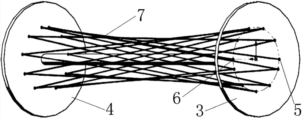
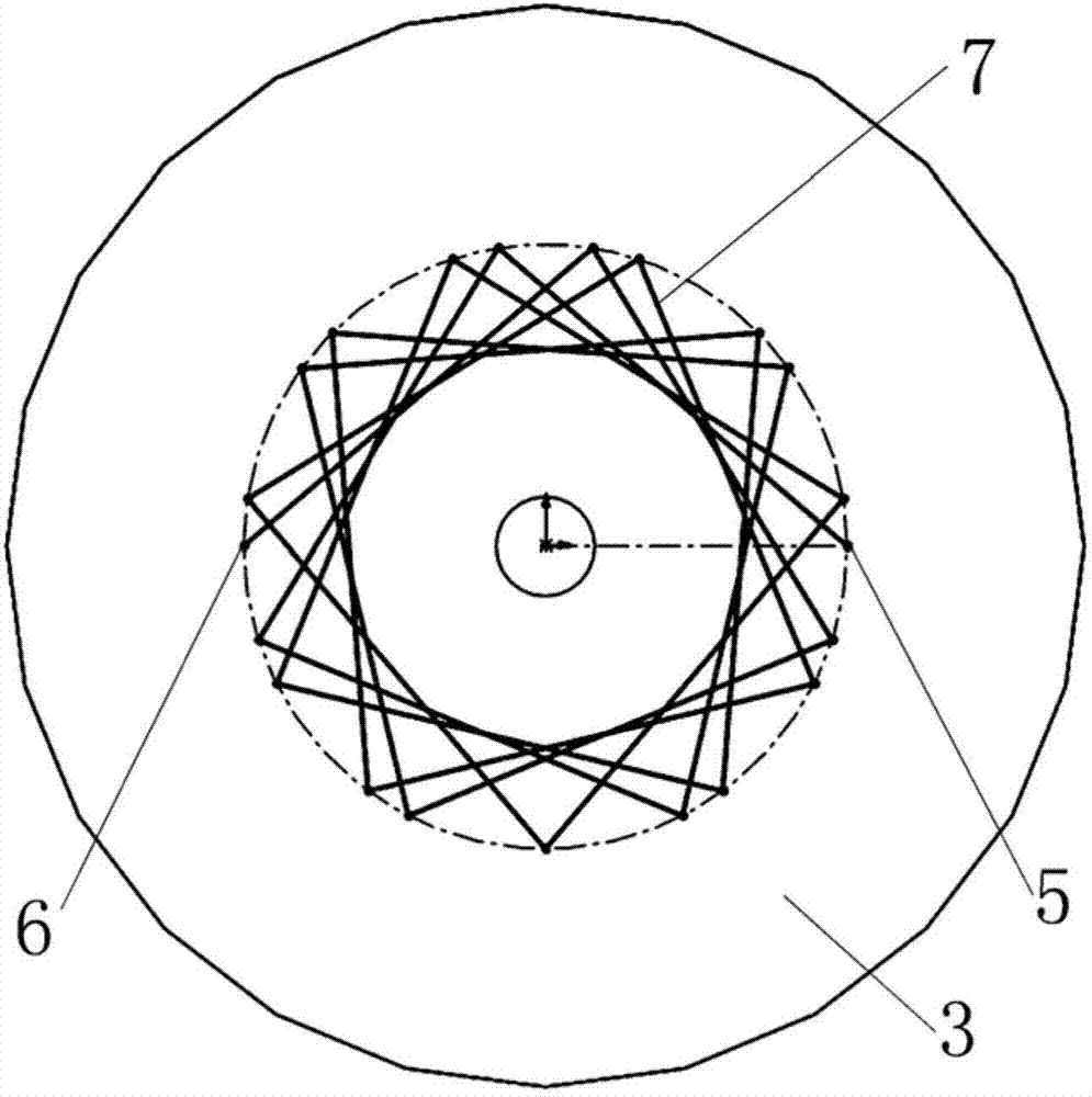
[0024] The trace gas sensor optical path system of this embodiment, such as figure 1 As shown, it includes an incident fiber collimator 1, an outgoing fiber collimator 2, a front reflector 3 and a rear reflector 4, and the front reflector 3 and the rear reflector 4 are concave spherical reflectors, and both Coated with a high-reflectivity film layer, and the concave spherical surface of the front reflector 3 and the rear reflector 4 are opposite and arranged on the same optical axis; the mirror surface of the front reflector 3 is provided with two parallel through holes, respectively for incident Through hole 5 and exit through hole 6, described incident through hole 5 and exit through hole 6 are arranged symmetrically with the optical axis of front reflector 3; Described incident fiber collimator 1, exit fiber collimator 2 are respectively The incident through hole 5 and the exit through hole 6 are coaxial, and are arranged on the outside of the front reflector 3 away from th...

Embodiment 2

[0027] A kind of trace gas sensor gas chamber of the present embodiment, such as Figure 5 As shown, it includes an absorption chamber 12 for gas absorption formed by the front end face 8, the rear end face 9 and the side wall 11. The front end face 8 and the rear end face 9 are respectively provided with A coaxial shaft hole, a front reflector 3 and a rear reflector 4 are respectively installed in the shaft hole, and the front reflector 3 and the rear reflector 4 are circular reflectors with a concave spherical surface, and the front reflector 3 and the rear reflector 4 are spherical reflectors. The concave spherical surface of the rear reflector 4 is opposite (the concave spherical surfaces are all facing the absorption chamber) and arranged on the same optical axis; the mirror surface of the front reflector 3 is provided with two parallel through holes, which are respectively the incident through hole 5 and the outgoing through hole. Holes 6, the incident through hole 5 and...


PUM


Abstract

The invention discloses a light path system of a trace gas sensor and an air chamber, wherein the light path system comprises an incidence optical fiber collimator, an emergence optical fiber collimator, a front reflector and a rear reflector, wherein the front reflector and the rear reflector are concave spherical mirrors, concave spherical surfaces are opposite, the mirror surface of the front reflector is provided with an incidence through hole and an emergence through hole parallel to each other; the incidence optical fiber collimator and the emergence optical fiber collimator are coaxial to the incidence through hole and the emergence through hole, are arranged at the outer side, far away from the rear reflector, of the front reflector, and are used for irradiating light beams emitted by the incidence optical fiber collimator to the rear reflector through the incidence through hole of the front reflector, the light beams are reflected by the front reflector and the rear reflector for a plurality of times, and then are irradiated out through the emergence optical collimator by virtue of the emergence through hole in the front reflector. According to the light path system provided by the invention, the light beams are reflected for a plurality of times between the front reflector and the rear reflector, and very high absorption optical path can be achieved within limited space, and the light path system is suitable for the optical gas sensor which has a compact structure and is used for accurately detecting trace gas.

Description

technical field [0001] The invention belongs to the technical field of optical fiber gas sensors, and in particular relates to an optical path system of a trace gas sensor, and also relates to a gas chamber of a trace gas sensor. Background technique [0002] Optical fiber gas sensor is a new type of gas sensor that appeared in the late 1980s. It has the characteristics of high measurement sensitivity, strong gas discrimination ability, fast response, and strong resistance to environmental interference such as temperature and humidity. It is the most promising An optical fiber gas sensor. The sensing part of the fiber optic gas sensor is an absorption gas chamber, and its design is directly related to the volume and persistence measurement sensitivity of the entire fiber optic gas sensor. [0003] Optical gas sensors based on the principle of gas absorption follow Beer-Lambert's law, that is, when a beam of parallel monochromatic light passes through a uniform non-scatterin...

Claims


Application Information

Patent Timeline
Patent Type & Authority Applications(China)
IPC IPC(8): G01N21/31G01N21/01
Inventor 赵彤宇刘鑫鑫詹方易周慧峰赵娟娟
Owner GL TECH CO LTD
Learn More